[inline_ad_block]
Worldwide experience with composite insulators is today considered on par with that of glass cap & pin insulators, with a population in service exceeding 20 million pieces. This population consists of insulators of different generations in terms of design, materials and production methods. Initially, lack of full understanding of composite technology, as was typical for some 1st and 2nd generation insulators, led to quality problems that included poor sealing, deficiencies in the interface between core rod and polymeric housing, flashunder, rod tracking and brittle fracture. These defects were acknowledged, investigated and eventually overcome in succeeding generations. In fact, an international project on infrared detection of interfacial defects, completed in 2002, had to rely on testing insulators with internationally simulated defects since no defective samples could be found in service at the time. More recently, however, as a result of rapid growth in production and with many new competitors having entered this market, composite insulators these days can be of much different qualities. As a result, the issue of quality of interface between fiberglass rod and silicone rubber housing has taken on renewed importance. Indeed, several service and after-service investigations have confirmed that the root cause of many recent failures in the field was poor adhesion at this critical interface. Significantly, this was clearly revealed by non-standard adhesion tests but not by existing IEC-based tests intended to verify the integrity of interfaces. Thus, quality is considered as not being fully covered by the existing IEC standards relating to such insulators.
[responsive_ad]
In 2008, the key product standards for composite line insulators (IEC 61109 and IEC 61952) were revised to align with the first edition of IEC 62217 – a standard which applies to all HV composite insulators and prescribes common tests including interface tests, housing tests, core tests, etc. IEC 62217 was last revised in 2012, with changes mainly in the UV ageing and the dye penetration tests. Moreover, both the wheel test and multiple stress tests were transferred to an IEC Technical Report. At present IEC 62217 is again under revision by MT19 TC36. It can be considered that the IEC standards mentioned above utilized knowledge obtained a decade or so ago and several tests in IEC 61109 have in fact remained largely unchanged since their introduction in the first edition. There seems a clear need to closely review these IEC standards, especially considering recent reported field experience.
Given this, a group of 9 European power companies (Amprion in Germany, Elia Group in Belgium &Germany, E.ON in Sweden, ESB in Ireland), Fingrid in Finland), REE in Spain, Statnett in Norway, Svenska Kraftnät in Sweden) and Vattenfall in Sweden), together with experts at the Independent Insulation Group, started a collaborative research project. One of the main goals was to develop a robust, effective test to evaluate level of adhesion. The following edited two-part report, contributed to INMR by I. Gutman, A. Dernfalk and P. Sidenvall of the Independent Insulation Group reviews what has been accomplished in this regard.
Service & After-Service Investigation
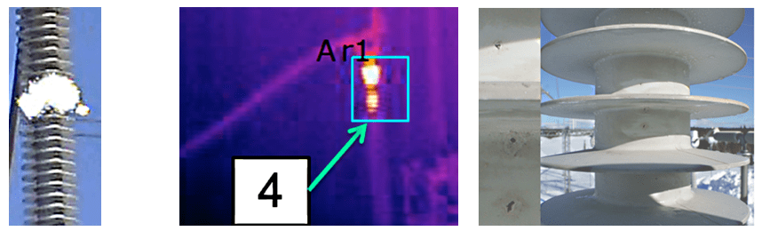
Recent service inspections of composite station post insulators revealed that, in some cases, corona observed by a UV camera was occurring not only close to the flange (as might be typical due to high electric field) but also at locations some distance from the high voltage end (see Fig. 1 left). Inspection of these same insulators with an IR camera revealed hot spots in these same places where corona had been detected (Fig. 1 middle). Further close inspection of de-energized insulators revealed multiple punctures of the housing in those locations where UV/IR detection had identified corona and hot spots (see Fig. 1, right). Later, during follow-up laboratory investigations low adhesion was detected for those insulators.
CLICK TO ENLARGE
The test program applied to insulators removed from service comprised:
1. Standard switching impulse test;
2. Non-standard adhesion test;
3. Standard steep-front impulse test;
4. Dissection and visual observation;
5. Standard dye penetration test.
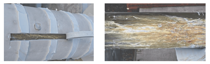
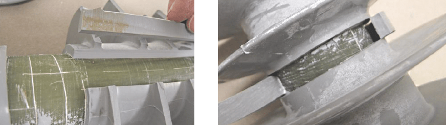
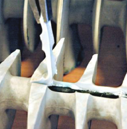
Two highly practical and simple methods for evaluating adhesion, i.e. the so-called ‘stripe-test’ and ‘square-test’ were also applied (see example of stripe test in Fig. 2, left). Testing adhesion of rubber to fiberglass by cutting and removing pieces of the housing is widely accepted and performed by many manufacturers as an internal quality check during production. Adhesion is considered to be poor (low) when the fracture is of the adhesive type, i.e. leaving the fiberglass rod open without any rubber left on its surface. This simple test revealed areas of low adhesion on insulators being tested and was likely the primary cause of the punctures. However, these same punctured insulators passed the standard switching impulse test with no indication that impulse voltage level had been reduced. Experience with the standard IEC steep-front test showed that this test was also not able to reveal insulators with only poor adhesion.
CLICK TO ENLARGE
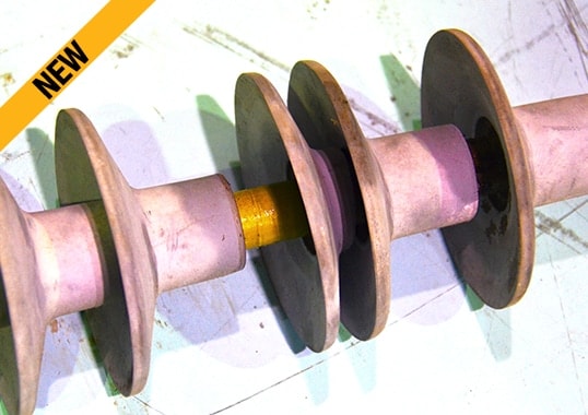
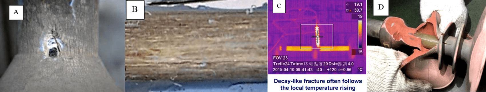
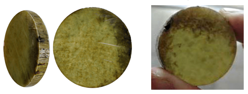
Dissection of samples, followed by visual inspection and a dye penetration test, confirmed that the damage under the silicone rubber was extensive (see Fig. 2, right). Discharge activity due to the semi-conductive path along the core rod had made the epoxy resin erode, leaving only the glass fibers. This type of failure mechanism was initially observed in China and their literature referred to it as ‘decay-like fracture’ (see examples of damages, possible reasons and possible diagnostic technique in Fig. 3). More recent publications have referred to the mechanism leading to such a phenomenon as ‘hydrolysis’. It is interesting to note the similar appearance of cross-sections of samples taken from insulators affected by this semi-conductive erosion investigated as part of this latest work and those from past problems reported in China (see Fig. 4). Dye penetration tests performed in Sweden verified the findings from dissection and penetration was observed only seconds after immersion. Blackened areas in the rod samples due to electrical activity matched those areas penetrated by the dye, confirming that they had become porous due to erosion of epoxy.
CLICK TO ENLARGE
CLICK TO ENLARGE
Service Case from Sweden
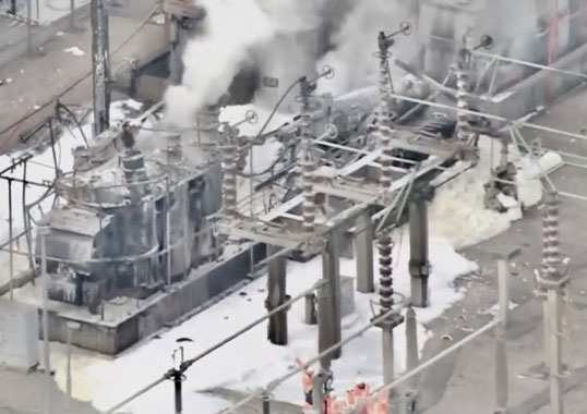
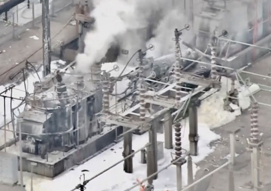
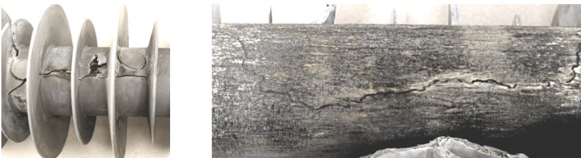
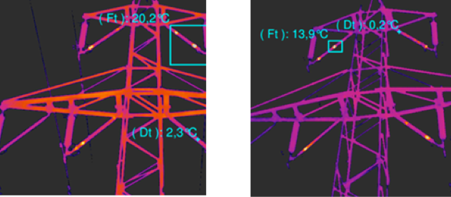
Early in 2016, two failures of composite line insulators were reported in Sweden. The failed units were inspected in the laboratory and the root cause was considered as poor adhesion between fiberglass rod and housing material. This was most probably followed by creation of an internal conductive path (tracking) along the internal silicone rubber/fiberglass rod interface (see Fig. 5, right). This eventually resulted in a ‘flashunder’ type of failure (see Fig. 5, left). The mechanism behind development of such damage was confirmed by in-service IR field inspections that revealed numerous hot spots on different insulators (see Fig. 6). Positions of these hot spots, located some distance from the fittings, can be explained by internal conductive paths, effectively ‘short-circuiting’ sections of the insulator.
CLICK TO ENLARGE
CLICK TO ENLARGE
Three new insulators from a larger batch of the same type were subsequently evaluated in the laboratory by sample testing. The test program comprised:
1. Visual and hydrophobicity inspection;
2. Non-standard adhesion test;
3. Standard steep-front impulse test.
The ‘stripe-test’ revealed low level of adhesion on all insulators tested in both longitudinal and radial directions (see Fig. 7).
CLICK TO ENLARGE
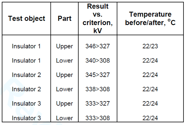
However, results for the standard steep-front test showed that all insulators formally passed this IEC test (see Table 1). Acceptance criteria require that the flashover voltage of each test specimen shall be greater than or equal to 90% of the reference flashover voltage. No puncture of any part of the insulator shall occur and maximum temperature rise shall be less than 20 K compared to the reference temperature determined prior to the power frequency tests.
CLICK TO ENLARGE
Service Case from Ireland
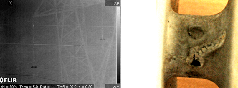
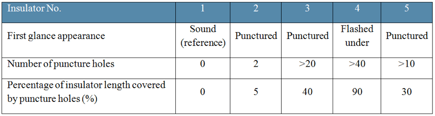
In Ireland, problems were experienced with composite long rod insulators on a 220 kV overhead line only a short time after installation, i.e. less than three years. Based on preliminary observations, failures were described as ‘flashunders’, indicating an internal type of breakdown. As a result, IR inspections were conducted and revealed several insulators with hot spots (see Fig. 8 left). Five insulators were subsequently removed from the line and taken for laboratory analysis. These included a reference insulator with no visible damage, three insulators with different numbers of punctures to housings (see Fig. 8, right) and an insulator where flashunder was suspected to have occurred. Visual inspection revealed multiple punctures, located differently for each insulator studied (see Table 2).
CLICK TO ENLARGE
CLICK TO ENLARGE
The test program for these insulators comprised:
1. Visual inspection;
2. Dry power frequency test;
3. High humidity power frequency test;
4. Non-standard adhesion test;
5. Dry power frequency test of bare fiberglass rod. This test was performed to evaluate the quality of the rod core.
The stripe test revealed that adhesion was not adequate for the two insulators tested. Level of adhesion was non-uniformly distributed along the insulator, being partially good and partially extremely weak. Moreover, at some positions the housing did not adhere to the fiberglass rod at all (see Fig. 9). In both cases, areas with poor adhesion represented an estimated 20 to 25% section of rod circumference along the entire length of the insulator.
CLICK TO ENLARGE
Note: Part 2 of this Investigation Will Appear in the INMR WEEKLY TECHNICAL REVIEW of Dec. 17.