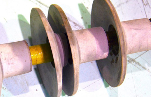
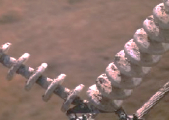
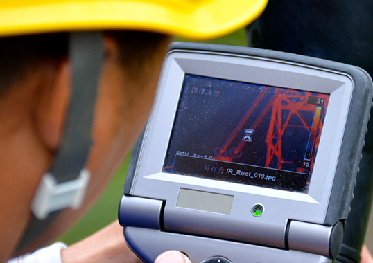
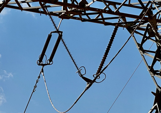
Service experience with composite line insulators is now considered on par with that of cap & pin insulators, with an estimated in-service population of some 20-25 million pieces of different generations. First and the 2nd generation composite insulators date back to the early 1980s and experienced several quality issues, as might be expected from any new technology. These included sealing problems, issues with the interface between fiberglass core rod and housing, flashunder, rod tracking and brittle fracture. All later came to be better understood and investigated to the point that most were overcome in succeeding generations. More recently, however, with many new players entering the marketplace and massive growth in industry production, composite insulators these days can again be of substantially different qualities. For example, past interfacial problems have again emerged since investigations have confirmed that the root cause of growing reported failures was poor adhesion in the critical interface between core rod and silicone rubber housing. While this problem was clearly revealed by non-standardized adhesion tests, it was not revealed by IEC tests intended to verify integrity of interfaces. As such, the issue of insulator quality is considered as not sufficiently covered in existing IEC standards.
In 2008, the main standards governing composite line insulators (i.e. IEC 61109 and IEC 61952) were revised to align with the first edition of IEC 62217 – the standard that applies to all HV composite insulators and prescribes common tests such as interface tests, housing tests, core tests, etc. IEC 62217 was last revised in 2012 with changes made mainly to the UV ageing test and the dye penetration test and with transfer of the wheel test and multiple stress test to an IEC Technical Report. IEC 62217 is presently again under revision, as is IEC 61109. It can be concluded that the above standards were based on knowledge obtained about 10 years ago and that several tests have remained largely unchanged since the first edition of IEC 61109. Thus, review of these IEC standards is warranted, especially in light of recent field experience.
The following edited 2019 contribution to INMR presented findings from a collaborative research project undertaken by European power companies together with the Independent Insulation Group in Sweden and intended to develop a robust and effective test to evaluate level of rod to housing adhesion. The TSOs and DSOs supporting this project were: Amprion (Germany), Elia Group (Belgium/Germany), E.ON (Sweden), ESB (Ireland), Fingrid (Finland), REE (Spain), Statnett (Norway), Svenska Kraftnät (Sweden) and Vattenfall (Sweden).
Recent Investigations
Service Case 1
In-service inspection of composite station post insulators revealed that corona activity observed in some cases occurred not only close to the flange (as might be expected due to excessive electric field) but also at some distance from the high voltage end (see Fig. 1, left). Infrared inspection of these same insulators then detected hot spots in the same locations where corona was being observed (see Fig. 1 center). Subsequent close-up visual inspection of de-energized insulators revealed multiple punctures in the locations where corona and hot spots had been identified. Follow-up laboratory investigation confirmed poor adhesion between the core rods and polymeric housings of these insulators

CLICK TO ENLARGE
The test program applied to insulators removed from service comprised the following:
1. Standard switching impulse test;
2. Non-standard adhesion test;
3. Standard steep-front impulse test;
4. Dissection and visual observation;
5. Standard dye penetration test.
Two simple and highly practical methods to evaluate adhesion, i.e. the so-called ‘stripe-test’ and ‘square-test’, were applied (see Fig. 2, left). Testing adhesion of rubber to fiberglass by cutting and removing sections of housing is performed by many composite insulator manufacturers as an internal check of production quality. Adhesion is considered poor when fracture is of the adhesive type, i.e. when the fracture is in the interface between the fiberglass rod and housing without any residue on surfaces. This simple technique clearly revealed areas of poor adhesion on insulators being tested and confirmed that this was likely the primary cause of the punctures. Nonetheless, punctured insulators still passed the standard switching impulse test with no indication of reduced impulse voltage level. Similarly, results of standard IEC steep-front testing also showed that this was not able to reveal insulators with a low adhesion.

CLICK TO ENLARGE
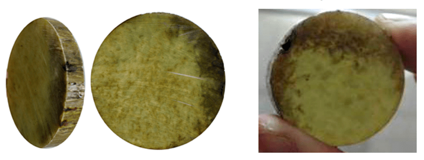
Dissection followed by visual inspection and a dye penetration test confirmed that damage under the silicone rubber was extensive (see Fig. 2, right). Discharge activity due to the semi-conductive path in the rod had partially eroded the epoxy resin, leaving only glass fibers. This type of failure was first observed in China and referred to in their literature as “decay-like fracture”. Fig. 3 illustrates examples of damage, possible causes and a potential diagnostic technique. More recent publications refer to the mechanism leading to such phenomenon as ‘hydrolysis’. It is interesting to note the virtually identical appearance of cross-sections of samples taken from affected insulators investigated in Sweden and China (see Fig. 4). Dye penetration tests conducted in Sweden then verified findings from the dissection, with dye penetration observed only seconds after immersion. Blackened areas in rod samples due to electrical activity corresponded to those areas penetrated by the dye, confirming that these areas had become porous due to erosion of the epoxy. Similar issues were detected in South Africa.

A: punctures in housing covering internal “decay-like fractures”;
B: appearance of fiberglass rod;
C: detection of internal failure by IR;
D: Poor adhesion believed to be root cause of damage.
CLICK TO ENLARGE
CLICK TO ENLARGE
Service Case 2
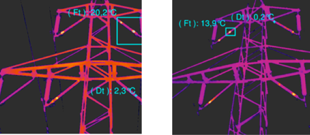
Failures of line composite insulators were experienced in Sweden in early 2016. Two such failed insulators were subsequently inspected in the laboratory and the root cause of the damage was determined to be weak adhesion between rod and housing. This was followed by formation of an internal conductive path (i.e. tracking) along the rod to housing interface (as shown in Fig. 5 right) and the so-called ‘flashunder’ failure mode (i.e. internal flashover), as in Fig. 5, left. The mechanism behind development of such damage was confirmed by field observation using IR inspection, which revealed hot spots on different in-service insulators (see Fig. 6).

CLICK TO ENLARGE
CLICK TO ENLARGE
Three new insulators from a larger batch of the same type were later evaluated in the laboratory by sample testing. The test program comprised:
1. Visual and hydrophobicity inspection;
2. Non-standard adhesion test;
3. Standard steep-front impulse test.
The ‘stripe-test’ revealed low level of adhesion on all insulators tested, both in longitudinal and radial directions, as illustrated in Fig. 7.

CLICK TO ENLARGE
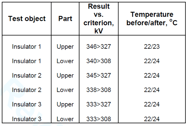
However, results for the standard IEC steep-front test (summarized in Table 1) showed that all insulators formally passed. Acceptance criteria require that the flashover voltage of each test specimen shall be greater than or equal to 90% of the reference flashover voltage. Moreover, no puncture of any part of the insulator shall occur and the maximum temperature rise shall be less than 20K compared to the reference temperature determined prior to the power frequency tests.
CLICK TO ENLARGE
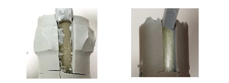
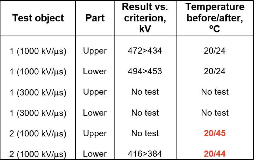
These results were later confirmed by other investigations, utilizing two different insulator types with poor adhesion (see Fig. 8 as confirmation of low adhesion characterized by typical adhesive fracture in stripe test). This time, insulators were tested both at standard (1000 kV/ms) and increased (3000 kV/ms) steepness. As in the earlier test, application of steep-front impulses did not result in puncture of any of the 6 samples tested. These insulators also formally passed the dry power frequency flashover test (evaluated for 3 samples), as summarized in Table 2. However, Insulator #2 did not pass according to the temperature criterion, i.e. it was more than 20 degrees hotter compared to reference measurements.
CLICK TO ENLARGE
CLICK TO ENLARGE
These results show that the IEC recommended steep-front test, even when performed at increased steepness of 3000 kV/s, still cannot reveal insulators with poor core to housing adhesion. One possible explanation is that this test was developed mainly to detect voids and inclusions in ceramic insulators and later applied to composite insulators, i.e. it was never intended for control of interface quality. However, a water immersion test might prove a valuable pre-stressor to reveal low core-housing adhesion and similar tests should therefore be investigated.
Service Case 3
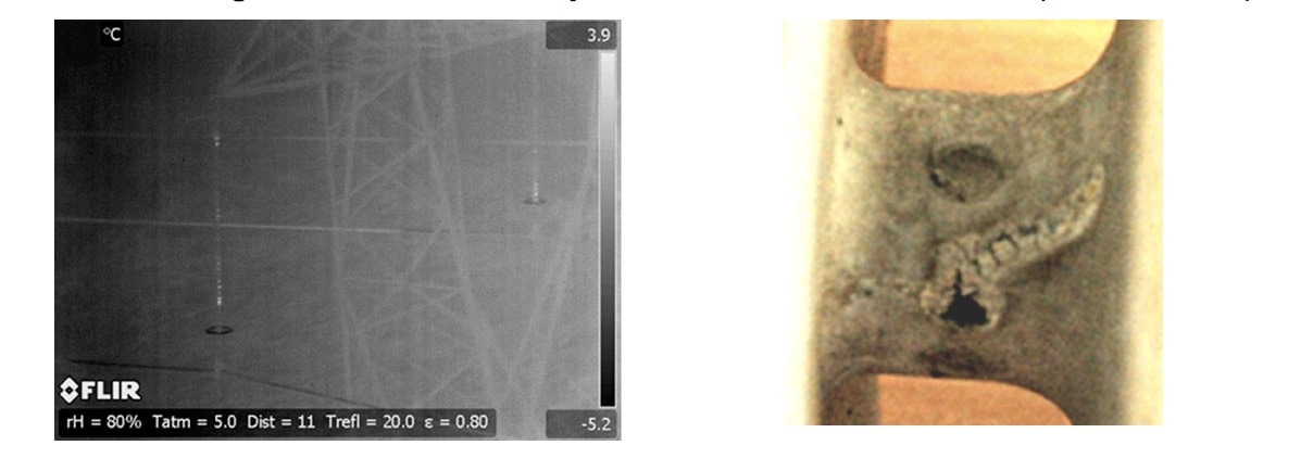
In Ireland, issues with line composite insulators were experienced on a 220 kV overhead transmission line less than three years after installation. Based on visual observation, the failures were described as ‘flashunders’. Since this suggested internal breakdown, IR inspections were organized and revealed several insulators with localized hot spots, (see Fig. 9 left). Five such insulators were then removed and taken for laboratory analysis. These included one reference insulator, without visible damage, three insulators having punctures in their housings (see Fig. 9, right) and one insulator in which flashunder was suspected to have already occurred. Visual inspection revealed multiple punctures of the housings, located differently for each insulator studied (see Table 3).

The test program for these insulators comprised:
1. Visual inspection;
2. Dry power frequency test;
3. High humidity power frequency test;
4. Non-standard adhesion test;
5. Dry power frequency test of bare fiberglass rod. This test was performed to evaluate quality of the rod.
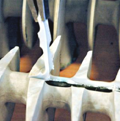
The stripe test revealed that rod to housing adhesion was not adequate in two of the insulators tested. Moreover, level of adhesion was non-uniformly distributed along the insulator, being partially good and partially weak. At some positions, the housing did not adhere to the rod at all (see Fig. 10). In both cases areas with low adhesion represented roughly 20-25% of the rod circumference along the insulator length.
CLICK TO ENLARGE
Basics of Adhesion
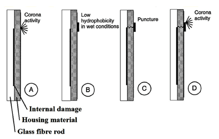
Past research revealed that weakness in some composite line insulators related to poor rod to housing adhesion, most probably the result of deficiencies during manufacture. In such cases the possible mechanism of what occurred in service could be explained as follows: initially, air-filled the space between fiberglass rod and silicone rubber and over time came to be filled with moisture due either to diffusion through the silicone rubber or due to poor sealing. Eventually, this initiated internal partial discharges that led to a partially conductive layer between rod and housing or within the rod itself. The HV potential was then transported from the HV fitting along the insulator. The short-circuited path increased electrical stress and this initiated corona that locally degraded hydrophobicity of the housing. Finally, this created either erosion or punctures through the housing. Fig. 11 provides a schematic of the mechanism. It is interesting to note that this same mechanism was first proposed in 2000, when testing composite insulators with intentionally produced defects (e.g. semi-conducting bands or channels simulating poor adhesion).
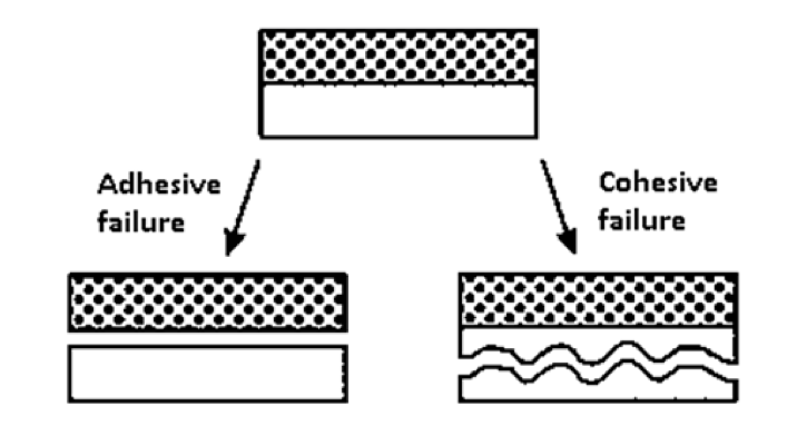
Proper adhesion between rod and housing should result in cohesive failure of the rubber rather than adhesive failure between rubber and rod. Both adhesive and cohesive failures are illustrated in Fig. 12.
CLICK TO ENLARGE
CLICK TO ENLARGE
If voids or improper adhesion exist in the interface between rod and housing, service life of an insulator will probably be reduced. While moisture in the form of vapor always penetrates the silicone rubber, this is a dynamic in-out process that should not affect insulator performance. However, if space for condensation of vapor is available at the interface, semi-conducting paths can be created.
Program for Development of New Adhesion Test
The goal of this research was to provide participating utilities with practical guidelines on how best to reveal low adhesion of composite insulators before putting them into service, based on limited sample testing of larger batches. These same test methods are being recommended for inclusion in design and sample tests in relevant IEC standards.
Choice of Test Objects
Test methods and criteria were selected based mainly on their being representative, robust and time-effective. The full array of test samples included the following three sets:
• Set 1 included three ‘academic’ groups of insulators from a single manufacturer containing intentionally different adhesion levels, achieved in the factory by means of proper primers, weakened primers or no primer at all;
• Set 2 used test objects taken from storage at STRI’s HV laboratory, including:
◊ Three different manufacturers but different years of production;
◊ Either after laboratory tests or removed from service;
◊ High Temperature Vulcanized (HTV) rubber and Liquid Silicone Rubber (LSR);
◊ Different rod diameters;
◊ Different levels of adhesion based on earlier investigations and stripe test results.
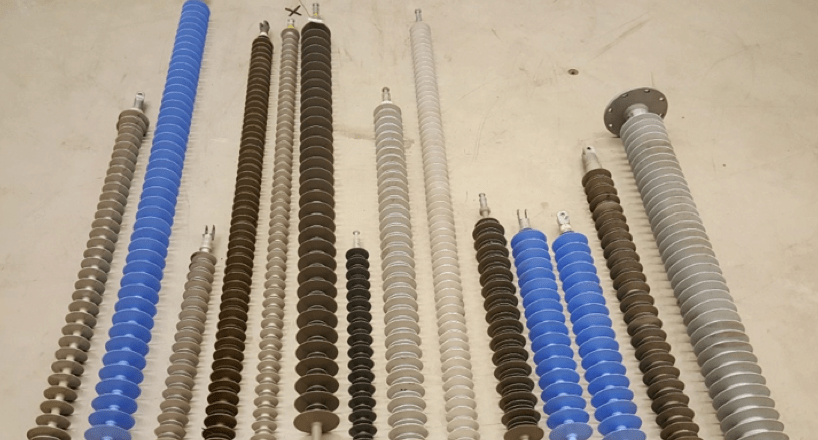
• Set 3 included test objects comprising 14 different insulators out of 58 units originally provided by power utilities from inventory (i.e. samples from batches already purchased). The following were considered in creating the final test array:
◊ Different designs (standard profile and alternating profile of sheds, different design of fittings, sealings, etc.);
◊ Different years of manufacturing (1999-2017);
◊ Different housing materials (HTV and LSR);
◊ Different voltage classes (123 to 420 kV);
◊ New reference insulators from storage (10 ps.) or used in service (4 ps.);
◊ Different diameters of glass fibre rods (i.e. mechanical classes), 16.5 to 90.0 mm;
◊ Different manufacturers with suspected different level of adhesion;
◊ Insulators contributed by different project participants (i.e. insulators from 7 utilities were used).
CLICK TO ENLARGE
Test Methods
Details of various test methods investigated are summarized below:
1. Stripe Test
Two parallel cuts, approx. 10 mm apart, are made through the rubber housing at the shank. This can be done along the insulator or around the shank. The resulting stripe is then pulled away from the underlaying fiberglass core using pliers, knife tip or by hand. Adhesion is judged subjectively based on appearance of fracture. If the fracture occurs inside the rubber (i.e. a cohesive failure), adhesion is considered as adequate. If fracture occurs along the interface between materials (i.e. an adhesive failure), adhesion is inadequate. Fig. 14 shows fractures with such different levels of adhesion.

CLICK TO ENLARGE
2. Water Penetration Test
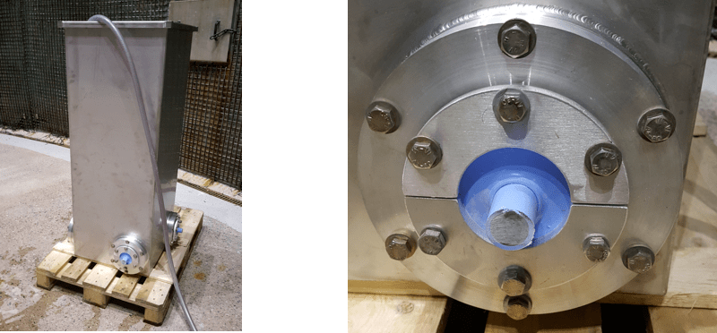
This method is based on a procedure described in a standard for optical fibre cables, i.e. IEC 60794-1-22, whose purpose is to evaluate longitudinal water tightness. During testing, the cross-section at one end of a test specimen is exposed to water at a pressure equivalent to 1 m water depth while the other end is left in ambient air. Tightness is evaluated by examining the ‘air side’ for traces of water penetration. In these tests this was done after up to 1500 h from the start. Fig. 15 shows the set-up used for insulator samples.
CLICK TO ENLARGE
3. Mechanical Stress Test
The idea behind this test came after accidentally damaging a composite insulator during application of artificial contamination during pollution testing. At the time, a long insulator was placed horizontally and supported by pairs of wheels placed at the ends and middle, allowing for continuous rotation by a motor drive. The same principle of cyclic mechanical shear stress of the interface was adopted for the present investigation as a means of pre-conditioning before evaluation of adhesion using the stripe test. A special tool was developed to allow for a defined mechanical load on the interface between housing and rod (see Fig. 16 left). This adjustable claw, fitted with two ball bearings to provide low friction at contact surfaces, was placed around the insulator shank. Level of shear stress is changed by adjusting separation and also the weight hung from the claw. The sample was placed horizontally and rotated around its axis by motor drive at 10 rpm (see Fig. 16 right).
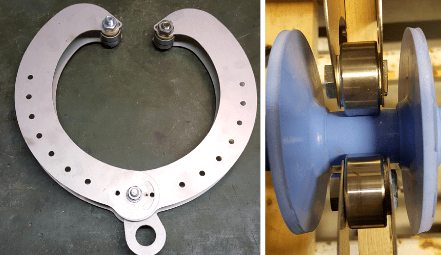
CLICK TO ENLARGE
4. Temperature Cycle Test
The potential effect of pre-conditioning by temperature cycling was studied when the samples were first immersed in boiling water for 6 minutes and then placed into a container with cold water close to 0°C for another 6 minutes. This was repeated 16 times. After completion of such cycling, adhesion was evaluated using the stripe test.
5. Water Diffusion Test
This test, standardized in IEC 62217, sees samples with rubber coating cut approximately perpendicular to the insulator axis using a diamond-coated circular saw and under running cold water. Specimens of only one core material were boiled together in the same container for 100 h (see Fig. 17 left). Each specimen was then put between electrodes, as shown in Fig. 17 right. Test voltage was increased at approximately 1 kV per second up to 12 kV. Voltage was then kept constant at 12 kV for 1 min and then decreased to zero. The acceptance criterion is that during the test no puncture or surface flashover shall occur. Also, the AC current during the whole test shall not exceed 1 mA (r.m.s.). It was decided to start with the standard method and, depending on results, try modifications, which included: increasing duration of boiling test from 100 h to 300 h; taking current measurements at both AC (during 1 min.) and DC (during 5 min.); taking measurements of DC current followed by measurements of AC current on the same sample.
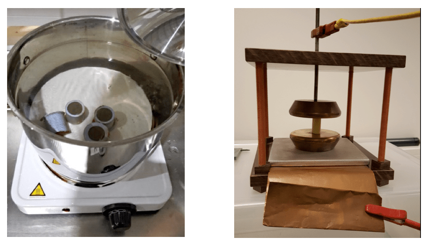
CLICK TO ENLARGE
6. Dye Penetration Test
A dye penetration test, also from IEC 62217, was carried out on the same type of specimens as in the water diffusion test, however with sample height of 10 mm. Specimens were placed in a vessel on a layer of glass balls and a solution of 1% by weight of Astrazon BR 2001 in methanol were poured into the vessel to a level of 2 to 3 mm higher than that of the balls. The criterion is that no dye shall rise through the specimens before 15 min have elapsed (see Fig. 18 left). In addition to the standard test, two modified tests were also performed: a test with increased duration of 16 hours (see Fig. 18, right) and a test with increased duration under pressure, originally taken from what is done when testing porosity of porcelain insulators.
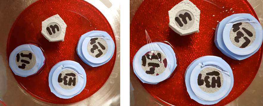
CLICK TO ENLARGE
7. Shear Stress Test
The purpose of this test, originally from a Russian standard, is to apply a defined shear stress along the interface between housing and rod and evaluating response. A short cylindrical sample is cut from the insulator, similar to the standard water diffusion test. The specimen is placed on a support plate with a circular hole (anvil) corresponding to the rod diameter plus a selected tolerance, resting on the rubber only (see Fig. 19 left). Applying force to the end of the rod subjects the interface to shear stress in the axial direction (see Fig. 19 right). For the present study, a small, manually operated hydraulic press having maximum rating of 20 tons was more than enough. To measure force, the press is fitted with a load cell. Since rubber material is highly elastic and will deform when being stressed, shear stress will not be constant along the sample length and will be highest at the anvil. Therefore, measurements of maximum shear stress per unit of perimeter length were used here only as a comparative measure of rank. Fig. 20 shows fractures that illustrate different levels of adhesion.
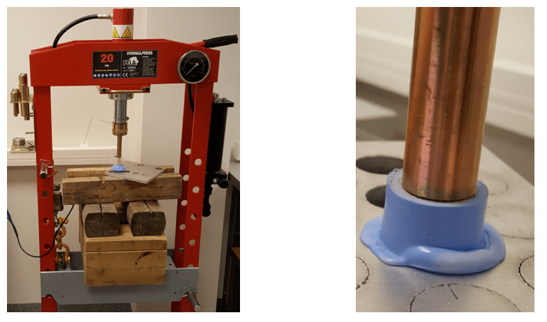
CLICK TO ENLARGE

CLICK TO ENLARGE
8. Pull-Off Test
In a pull-off test, adhesion between materials is evaluated by pulling a part of the shed, as in the practical test set-up shown in Fig. 21. Tests were performed using a standard tensile test machine with maximum pulling capacity of 10 kN and allowing for controlled application of mechanical load. For this study, the instrument was set at a fixed rate of elongation (i.e. 50 mm/min) while recoding applied force. After completion of the mechanical test, ultimate breaking stress was calculated, i.e. maximum applied force divided by material cross-section area at rubber-rod interface, and used for further analysis. Fig. 22 shows typical adhesive/cohesive fractures in shear stress tests.
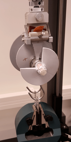
CLICK TO ENLARGE
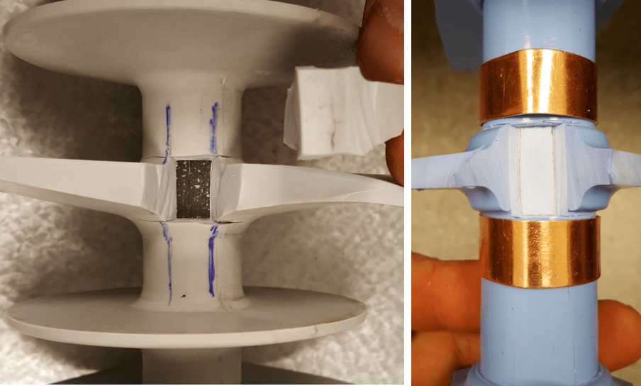
CLICK TO ENLARGE
Test Results
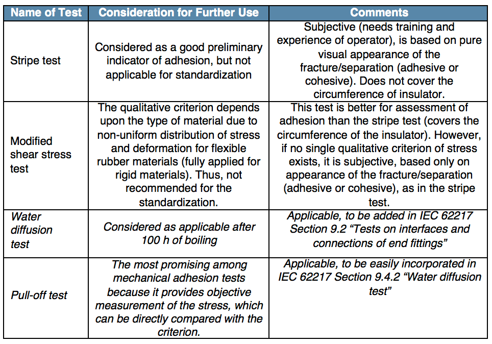
Table 4 presents analysis of the first round of test results and made it possible to concentrate on the most promising tests.
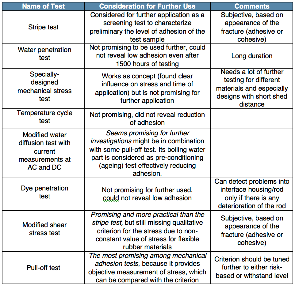
CLICK TO ENLARGE
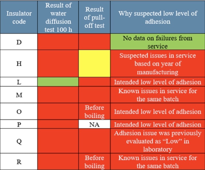
Table 5 presents a summary of all results obtained (i.e. the second round of selecting appropriate tests), using ‘traffic light principles’, where red indicates ‘failed’. To allow all results to be compared, simple preliminary acceptance criteria were proposed for ranking. In the case of the water diffusion test, for example, this was a current lower than 0.25 mA while for the pull-off test this was a stress higher than 1.5 N/mm2. These criteria were proposed stricter after further testing. The following abbreviations are used in Table 5:
• Different materials (H = HTV; L = LSR)
• St = stripe test
• Sh. = shear stress test
• Shear stress (F = Force, i.e. maximum stress; A = Appearance of fracture)
• WD = Water diffusion test
• P = Pull-off test
The analysis concentrates on results after 100h of boiling. This duration was chosen since it directly corresponds to the requirement in the present IEC 62217, which facilitates further standardization. Insulators D-I-L-M had suspected low levels of adhesion based either on past service records or intentional manufacturing of academic samples. The detection rate for both the pull-off test and the water diffusion test, considered separately, was 3 of 4, i.e. 75%. It is therefore proposed to use both tests for final evaluation of insulators in order to best identify insulators of poor quality. The actual physics of the complex interaction of environment and specific insulators having some specific combination of materials, technology and production quality is still not fully understood. This is why detection rate for any of the tests investigated is not 100%. As such, both tests are needed for a definitive evaluation of adhesion. Final considerations are presented in Table 6.
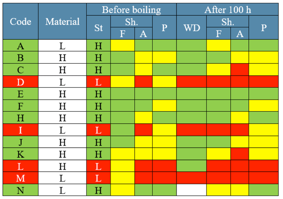
CLICK TO ENLARGE
CLICK TO ENLARGE
Level of Test Maturity
Considering all test results obtained, it is recommended that both pull-off and water diffusion tests be used for final evaluation of insulators with the goal of revealing those insulators with only poor rod to housing adhesion. The place for these tests in IEC 62217 and IEC 61109 (which are under revision) is proposed in Table 6. Implementation of this new method will require minor changes in the text of these standards. It is also proposed to use the same specimen for both tests, which contributes to cost-effectiveness of the procedure.
The representativity of the proposed test was evaluated by analysis of the origin of samples, identified as having low levels of adhesion either by past service experience or verified by other tests performed earlier. Results are presented in Table 7, comprising all collected experience. The preliminary criteria proposed above were applied (RED colour indicates ‘failed’). For the majority of insulators evaluated, except ‘D’, which requires further investigation, results of these tests were relevant (i.e. representative) since weak adhesion was detected by the tests being proposed.
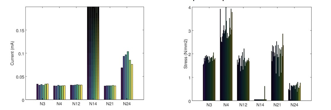
Repeatability of a test procedure is a measure for how well tests can be repeated in the same laboratory and still yield the same results. Fig. 23 shows an example of the water diffusion test (three measurements per sample). To better investigate repeatability, 6 new samples from 5 different manufacturers were chosen (designated as N3-N24). These included 2 insulators with low levels of adhesion and 4 with high levels of adhesion, as verified by stripe tests. To obtain a statistically valid result, samples were taken by cutting two sheds from the top-middle-bottom portions of each insulator, resulting in 6 samples per insulator. After performing current measurements, 4 specimens for pull-off tests were created from each sample, thus giving a total of 6×4=24 specimens per insulator. Test results, presented in Fig. 24, are repeatable, with reasonable spread. Spread of results for insulators with low adhesion is significantly higher than for insulators with high adhesion. This can be explained by possible high non-uniformity of areas with different levels of adhesion along these insulators.

Repeatability of a test procedure is a measure for how well tests can be repeated in different laboratories and provide the same results. A detailed test program was developed and distributed to university or independent test laboratories in the Czech Republic, Germany, Hungary and Sweden, together with an identical set of 5 test samples (sections of insulators with a shed). In the case of all laboratories, only personnel who had not earlier been involved in such tests conducted the RRT tests. Preliminary findings are positive but not yet fully documented. Thus, only the first result for the water diffusion test is presented in Table 8, by way of illustration. Again, red indicates a ‘failed’ test, this time with an updated criterion of less than 0.1 mA. A more comprehensive evaluation of repeatability is expected during 2020.

Cost-effectiveness of tests can be achieved in two ways. First, it can be proposed to remove the entire Clause 9.2 from IEC 62217: “Tests on interfaces and connections of end fittings”. These tests include sequence of water immersion pre-stress test, steep-front impulse test and diagnostic dry power frequency test. Since the steep-front test is particularly complex and also costly, it is proposed to instead use small sample tests, i.e. water diffusion, which is applicable to simultaneously evaluate core/housing interface and core alone, as well as the pull-off test. This was discussed at a WG meeting to revise IEC 62217 but not supported by the majority of members because defects other than poor adhesion can be revealed using the steep-front test. As such, as a second option, only a slight modification is proposed in IEC 62217/61109 based on small-scale, less costly tests.
Summary
Several methods were investigated to find the most promising tests to reveal insulators with poor rod to housing adhesion, thereby allowing low-quality insulators to be ‘filtered out’ before they reach power networks. A combination of two tests (i.e. water diffusion and pull-off) is considered as representative, repeatable, cost-effective and preliminarily reproducible, i.e. fulfilling all four IEC requirements for any type of test. The exact place for these new test methods in IEC 62217 and IEC 61109 (both presently under revision) is still under discussion, but their implementation will require only minor changes to the text of the two standards.
References
- Gutman, T. Hayashi, A. Phillips, A. Pigini, J. Seifert, F. Schmuck, M. R. Shariati, V. Sklenicka: “Guide for the Assessment of Composite Insulators in the Laboratory After Their Removal from Service”, Working Group B2.21, CIGRE TB 481, December 2011
- Gutman, K. Halsan, L. Wallin, T. Goodwin, G. Sakata: “Application of Helicopter-Based IR Technology for Detection of Internal Defects in Composite Insulators”, World Congress & Exhibition on Insulators, Arresters & Bushings, Crete, 11-13 May 2009
- “Techniques to Inspect Insulators Take on Growing Importance at STRI”, Insulator News & Market Report, Vol. 10, No. 3, May/June 1998
- Gutman, J. Lundengård, C. Ahlrot: “Need of standardized adhesion test for composite insulators: lessons learned from service experience”, 20th ISH-2017, Buenos Aires, Argentina, August 28 – September 01, 2017, paper 145
- Radosavljevic, I. Gutman, C. Ahlholm, P. Sidenvall: “Ageing and deterioration of composite post insulators exposed to high electric field in 220 kV and 400 kV switchyards in Swedish network”, 2017 CIGRE SC B3 Colloquium, Recife, Brazil, 18-20 September 2017
- Gutman, P. Sidenvall, T. Condon, P. Flynn, P. Shiel: “Evaluation of composite insulators with internal deterioration: lessons learned from service and after-service testing”, CIGRÉ Winnipeg 2017 International Colloquium & Exhibition, Winnipeg, Canada, September 30 – October 6, 2017, paper 142
- IEC 61109, Ed. 2.0, “Insulators for overhead lines – Composite suspension and tension insulators for a.c. systems with a nominal voltage greater than 1 000 V – Definitions, test methods and acceptance criteria”, 2008
- IEC 61952, Ed. 2.0, “Insulators for overhead lines – Composite line post insulators for a.c. systems with a nominal voltage greater than 1 000 V – Definitions, test methods and acceptance criteria”, 2008
- IEC 62217, Ed. 1.0, “Polymeric HV insulators for indoor and outdoor use – General definitions, test methods and acceptance criteria”, 2005
- IEC 62217, Ed. 2.0, “Polymeric HV insulators for indoor and outdoor use – General definitions, test methods and acceptance criteria”, 2012
- IEC/TR 62730, Ed. 1.0, HV polymeric insulators for indoor and outdoor use tracking and erosion testing by wheel test and 5 000h test, 2012
- IEC 61109, Ed. 1.0, AMEND 1.0, “Composite insulators for a.c. overhead lines with a nominal voltage greater than 1 000 V – Definitions, test methods and acceptance criteria”, 1995
- Jiafu Wang, Xidong Liang, Yanfeng Gao: “Introduction to decay-like fracture of composite insulator”, 18th ISH-2013, Seoul, Korea, 25-30 August 2013, OE3-06
- Liang Xiding: “Survey of Composite Insulators Experience in China”, World Congress & Exhibition on Insulators, Arresters & Bushings, Munich, Germany, 18-21 October 2015
- Zhang, Z. He, Y. Liao, G. Wang, B. Luo: “Research on the adhesiveness between core rod and sheath for composite insulators on the transmission lines”, 13th INSUKON-2017, Birmingham, UK, 16-18 May 2017, p.p. 260-265
- Xidong Liang, Weining Bao, Yanfeng Gao, Shaohua Li, I. Gutman, C. Ahlholm, M. Radosavljevic, W. Vosloo: “A new type of failure of composite insulators: service experience, degradation characteristics, root cause, experimental simulation and countermeasures”, abstract of CIGRE Report for CIGRE Session 2020 submitted to CIGRE via Chinese NC, 2019
- Gutman, A. Dernfalk, P. Sidenvall, J. Lundengård: “New Test to Reveal Level of Rod/Housing Adhesion for Composite Insulators”, 21st ISH-2019, Budapest, Hungary, August 26-30, 2019, paper 749
- Schmuck, S. Aitken and K. Papailiou: “A Proposal for Intensified Inspection and Acceptance Tests of Composite Insulators as an Addition to the Guidelines of IEC 61109 Ed. 2: 2008 and IEC 61952 Ed. 2: 2008”, IEEE Transactions on Dielectrics and Electrical Insulation, Vol. 17, No. 2, April 2010, p.p. 394-400
- IEC 60794-1-22, “Optical fibre cables – Part 1-22: Generic specification – Basic optical cable test procedures – Environmental test methods”, Ed 2.0, 2017
- Russian State Standard P 55189-2012: “Line suspension composite insulators. General technical requirements”, Moscow, Standardinform, 2014 (in Russian)
- Dernfalk, P. Sidenvall, I. Gutman: “Development of the test capable to reveal level of adhesion between fibreglass rod and housing of composite insulators “, CIGRE-IEC 2019 Conference on EHV and UHV (AC & DC), April 23-26, 2019, Hakodate, Hokkaido, Japan, P1-10
- Ahlrot, P. Aparicio, A. Berlin, T. Condon, J.-F. Goffinet, I. Gutman, K. Halsan, R. Radosavljevic, K. Varli, K. Välimaa: “New test procedure intended to evaluate adhesion of core/housing interface of composite insulators”, abstract of CIGRE Report for CIGRE Session 2020 submitted to CIGRE via Swedish NC, 2019

