High-voltage direct-current technology facilitates transmission of bulk energy with relatively low impact infrastructure as well as reduced losses. Moreover, the outstanding performance of modern HVDC solutions also offers other technical, economic and environmental benefits. At the same time, HVDC power transmission has become increasingly competitive with AC, especially over long distances. These reasons are why HVDC is seen as the backbone for what experts and government officials have called the ‘super grid’ (i.e. a high-capacity transmission network) that will efficiently move electrical power to key load centres. In Germany, for example, wind energy parks along the North Sea need connection to energy-hungry industries in the South. All scenarios have revealed that transmission capacity has to be increased, even as public acceptance of new overhead line projects is a challenge. Therefore, various compact solutions and T&D technologies having high efficiency are required. One of the most important of these is a hybrid solution having AC and DC overhead lines on common towers. But where such a solution cannot be realized, there are growing needs to lay cables. It is therefore essential to provide testing solutions to manufacturers and also to utility end users. Heiko Jahn and Uberto Vercellotti of CESI Group’s Testing & Certification Div. in Germany and Italy present an overview of recent testing of extruded cables for DC applications.
Test Procedures
IEC standards already exist for extruded cables for AC applications but not to the same extent for DC. Recommendations for testing DC cables were presented in the past within CIGRÉ (i.e. Electra #72 in 1980 and #189 in 2000). These were based on then available paper-insulated cables, oil-filled paper insulated cables and internal gas pressure cables. Later, increased market demand for extruded DC cables for higher transmission voltages resulted in the CIGRÉ Reports #219 and #496. Moreover, IEC 62895 “HVDC power transmission cables with extruded insulation and their accessories for rated voltages up to 320 kV for land applications – Test methods and requirements” has since been under preparation. This standard applies the same basic philosophy as for extruded AC cables, with the following main tests to be performed:
1. Development Tests (DT)
These are performed during the development phase of the cable system;
2. Routine Tests (RT)
Manufacturers perform these tests on each manufactured component to verify that the component meets specified requirements;
3. Type Tests (TT)
These tests are carried out before supplying a cable system and are to confirm satisfactory performance to meet the intended application;
4. Long Duration/Pre-Qualification Tests (PQ)
These are performed to demonstrate reliability of the complete cable system in regard to long-term performance;
5. After-Installation Tests (On-Site Tests)
These are intended to demonstrate the integrity the cable system as installed.
Besides the various tests carried out by manufacturers (i.e. development, routine and sample tests), it is recommended that further tests be conducted to confirm the functionality of the cable system (i.e. type tests and pre-qualification tests). These are typically performed at independent external laboratories to increase confidence by the utility in the test reports being provided. One major difference of DC cables compared to already introduced AC cable systems is their expected behaviour during polarity reversal of test voltage. This is important since the high specific resistivity of XLPE materials causes accumulation of space charges and therefore temporary by electric field strength.
Test Set-up
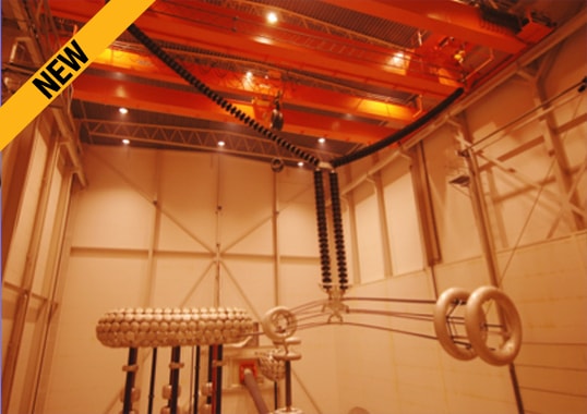
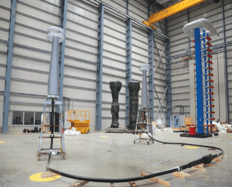
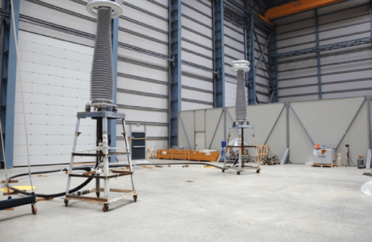
To meet increasing demand for tests on extruded HVDC cables, specialized laboratories have been built to carry out such tests. For example, a recently built laboratory in Mannheim, Germany is now one of the world’s largest HVDC cable and accessory test facilities and allows development tests, type tests and long duration tests (PQ) to be carried out for rated voltages up to 600 kV DC. Overall hall size is 60x26x21 m (Lx- WxH) and three independent areas of 26×20 m each can be separated by movable walls to allow smaller test facilities with different HVDC generators, i.e. 800 kV, 1200 kV and 1600 kV.
CLICK TO ENLARGE
CLICK TO ENLARGE
Other features include a 3000 kVpk/300 kJ impulse generator, electromagnetic shielding for PD measurements, cable ducts for installation outdoors (up to 6000 m²) and two 10 ton cranes for sample handing. Up-to-date technical recommendations can be specified while tailor made solutions based on client specifications can also be applied.
Apart from load cycle tests, superimposed impulse voltage tests (specific for both LCC & VSC systems), long duration tests and superimposed switching impulse voltage tests, short circuit tests and internal arc tests, as increasingly required for safety reasons, can also be carried out at the adjacent high power laboratory.
A test protocol for DC extruded cables with the aim of comparing results of such tests with current knowledge on MIND (mass-impregnated non-draining) cables has been developed by Italian TSO, Terna, together with the University of Bologna and CESI. The main interest was a first approach to compare DC extruded cables and MIND cables in terms of endurance to polarity reversal. Specific numerical models for evaluating service life of both cable types, jointly developed between Terna and the University of Bologna, were used to select accelerated test duration and number of polarity reversals to be performed. The test program was comprised of two main segments: an ageing segment and a sustained polarity reversal stress portion (formally a second ageing section). The first ageing segment was based mainly on a procedure for cables to be installed in systems that allow voltage polarity reversal. Specific accelerated ageing factors were then selected to obtain information on ageing of the cable under test within a shorter time period (i.e. 4 months instead of the usual 12). In regard to the second segment, a sustained polarity reversal stress section was formally adopted based on years of experience testing MIND cables.
Recent Test Experience
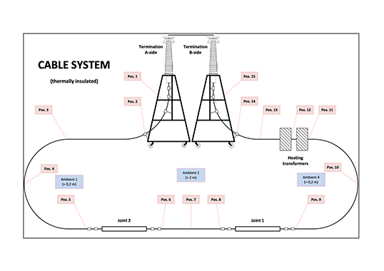
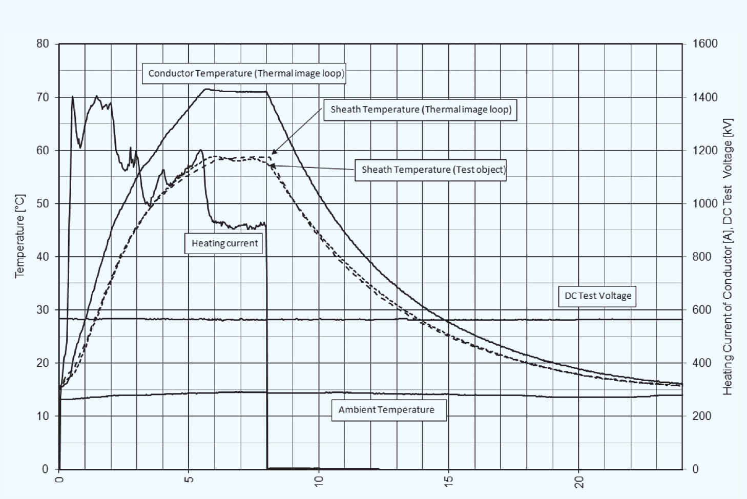
Physical installation of cable loops within the laboratory is not much different from that used for AC cable systems. Since temperature difference between sheath and conductor was limited to 30K, additional heating of the sheath had to be installed. It took several cycles without applied voltage to establish correct test parameters. Fig. 1, for example, shows test parameters typically measured during one load current test cycle with DC voltage applied and conductor heated with induced AC current.
CLICK TO ENLARGE
The difference between sheath and conductor temperature is limited since this thermal drop is critical for the material chosen by any specific cable manufacturer. The manufacturer therefore has to indicate this before starting the cycles – a situation that differs from AC thermal cycling procedures. Further experience was that, as during all tests with DC, all objects in the laboratory are to be solidly grounded to avoid electrostatic charging by influence. Care also has to be taken to shield the installation to avoid high dielectric field strength, which causes inception of corona discharges.
Conclusions
Tests have been underway over recent years to gather more and more information about state-of-the-art in extruded HVDC cables under polarity reversal stress. While the outcome of such tests is clearly confidential among the parties involved, it should be noted that research has been undertaken by Terna and others to increase knowledge pertaining to innovative materials and components used for HVDC cable systems. This information will not only be of great benefit to cable suppliers but also for TSOs and other end users of this technology, where extremely high reliability is demanded. Availability of suitable Third Party Laboratories represents a fundamental step forward in the HVDC cable system market where extruded cable systems have gained a rapidly increasing presence due to many land and especially submarine HVDC cable links of this type being commissioned.

