Surge Arrester Sizing for SubTransmission Systems Using Grounding Transformers by Xuan Wu
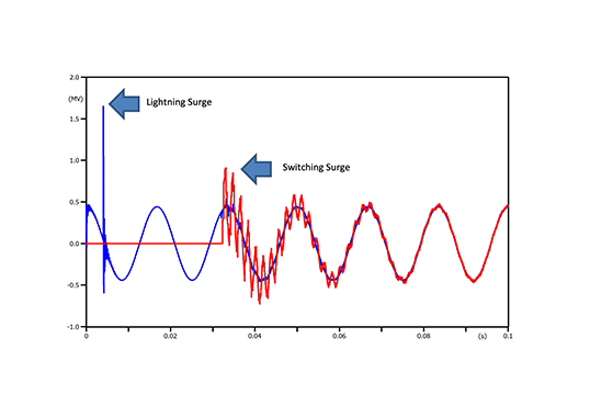
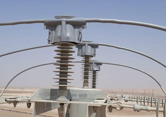
A sub-transmission system is considered effectively grounded at a particular location if the ratio between its zero-sequence reactance (X0) and its positive-sequence reactance (X1) satisfies 0 < X0/X1 < 3. A grounding transformer would lower the overall zero-sequence impedance of the power system at the grounding transformer location, X0, to a desired value. Lowering the X0/X1 ratio at a particular system location will result in higher line-to-ground fault current at that location. The higher fault current will allow for easier and better relay protection coordination with protective equipment downstream. However, even if grounding transformers improve relay protection coordination, the decision to install grounding transformers and the selection of their impedance to increase line-to-ground fault current at a particular system location must be evaluated case-by-case. This presentation deals with selecting and applying an appropriate surge arrester to protect corresponding equipment and focuses on temporary overvoltage evaluation, which governs the selection process for arresters for ungrounded sub-transmission systems. The specific case involves the Appalachian Power Region of AEP’s service territory, which includes substations that have autotransformers with ungrounded delta tertiary windings. Use of the tertiary winding varies from station to station but, whatever the specific scenario, grounding transformers are used to detect line-to-ground faults and stabilize the neutral during system ‘unbalanced’ situations, such as fault conditions.

