The basic requirements for heavy-duty distribution class arresters that protect power networks against atmospheric overvoltages, irrespective of technical standard, include: Ures/Ur=1.65-3.3; 2 mS long-duration current withstand of 250-400 A; and a 4/10 μS high current withstand capability of 100 kA. Up to now, most manufacturers of such arresters have used metal oxide varistor discs with 42 mm diameter and a potential gradient of about 220 V/mm.
Recent years however have been marked by continuous improvements in manufacturing technology for varistors. These have enabled lower manufacturing costs through reducing diameter as well as height of the MOV stack – while still meeting all required technical parameters.
Xi’an Tian Gong Electric (TGE), a manufacturer in China, has developed new glass-glazed metal oxide varistors with 36 mm diameter (D36) suitable for heavy duty arresters that meet the requirements of IEC 60099-4:2014, IEEE C62.11-2020 and GB11032-2020. The goal was to allow more compact heavy-duty distribution arrester designs and thereby reduce costs. This edited article, contributed by experts at TGE, introduces the technical performance of this new type of MOV and provides guidance for users based on test results.


Metal Oxide Varistor Performance
Basic Performance
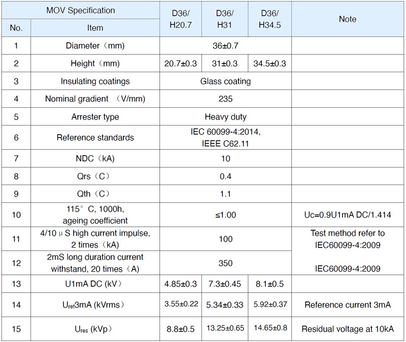
D36 is a special series of MOVs developed by TGE that meet IEC 60099-4: 2014 as well as the IEEE standard for heavy duty distribution arresters. Table 1 summarizes the basic performance of this new MOV.
Protective Characteristics
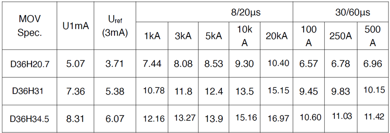
Table 2 shows the residual voltage of these MOVs at 8/20μs lightning impulse and 30/60μs switching impulse.
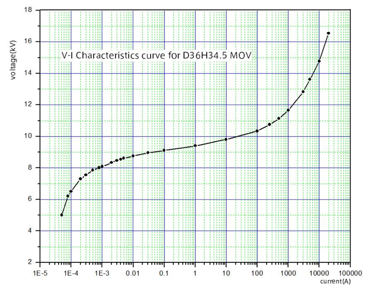
Typical V-I Characteristic Curve
Fig. 1 shows the typical V-I characteristic curve of D36/H34.5 MOVs.
Repetitive Charge Transfer Characteristics
D36 MOVs were subjected to a charge transfer test according to the method specified in IEC60099-4: 2014 standards (as shown in Fig. 2).
D36 MOV Qrs Test Results
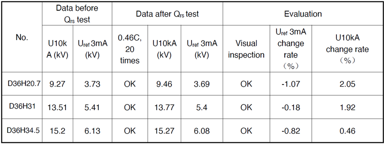
Note: Test data of each specification is average value of 5 pieces.
2 ms Long Duration Current Withstand
Table 4 provides the residual voltage and reference voltage data of D36/H20.7, D36/H31 and D36H34.5 MOVs before and after withstand (18 times 350A 2mS long duration current).
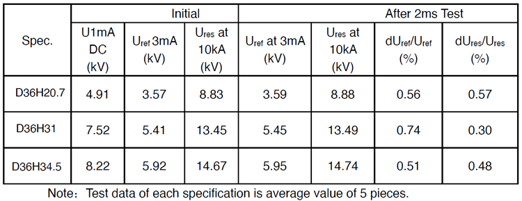
Test Data Before & After 2mS Long Duration Current

4/10 μs High Current Withstand
Table 5 shows the residual voltage and reference voltage test data of D36/H20.7, D36/H31 and D36/H34.5 before and after withstand 2 times of 4/10μs high current impulse.
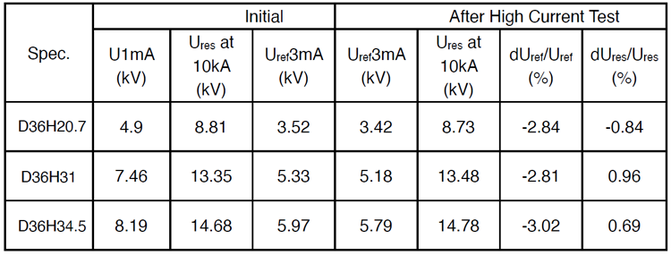
Test Data Before & After 2 times 4/10 μs High Current Impulse
Stability at Long-Term Operating Voltage
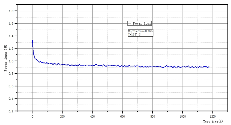
To demonstrate MOV stability under long-term continuous operating voltage, an accelerated aging test was performed on 3 pcs of D36 MOV using a test procedure complying with IEC60099-4:2014. Test data is shown in Fig. 3.
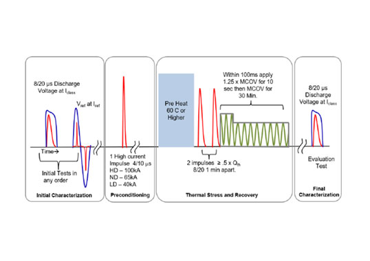
Operating Duty Test Performance
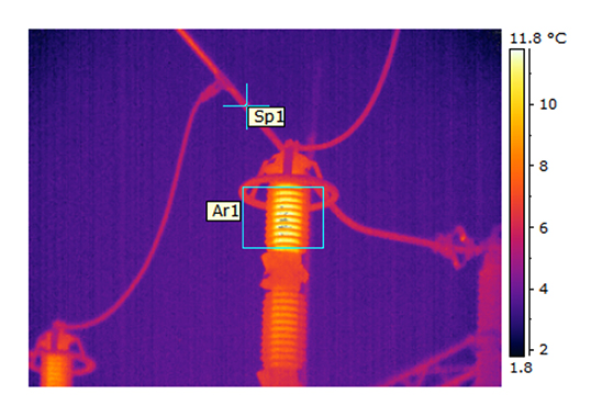
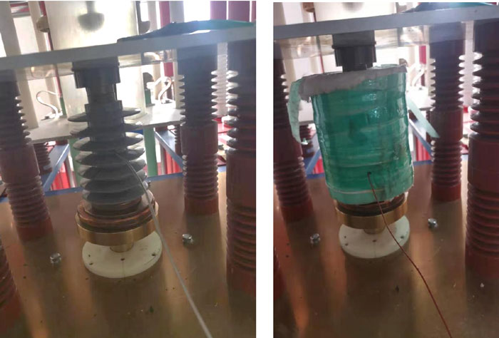
Before the operating duty test, the heat dissipation characteristics of the thermal prorated section and arrester were evaluated. Power frequency voltage was applied to a 6 kV arrester and to the thermal section equipped with the 6 kV arrester core. After about 2h, the temperatures of the arrester and the thermal section reached more than 120°C respectively. The samples were then allowed to cool at room temperature. Fig. 4 shows the test specimens with heat dissipation characteristics, along with a sample of the thermal dissipation characteristics.
Fig. 5 shows that the heat dissipation rate of the section is slower than that of the arrester. Therefore, the operating duty test performed by this section can represent the operating duty characteristics of the arrester.
The operating duty test program in Fig. 4 shows that each arrester section contains two pieces of D36/H22 MOVs. In order to verify the operating duty test margin of the MOV, different rules for the value of the rated voltage were designed, including different continuous operation voltage value rules and different times of high current impulses. In addition, to increase test severity, the preheating temperature of the section before applying thermal charge was increased from 60°C (as specified in the standard) to 75°C.
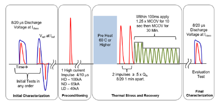
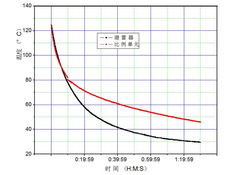
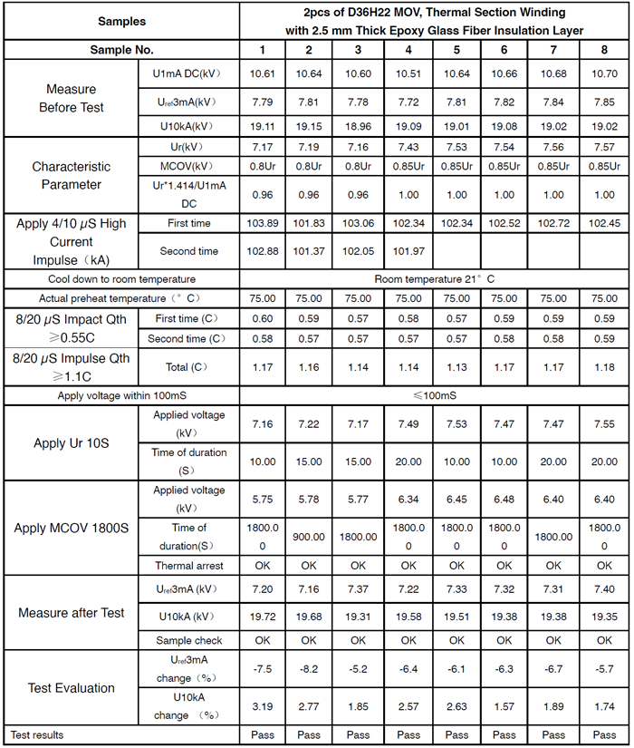
Fig. 6 shows the thermal prorated section and the arrester.
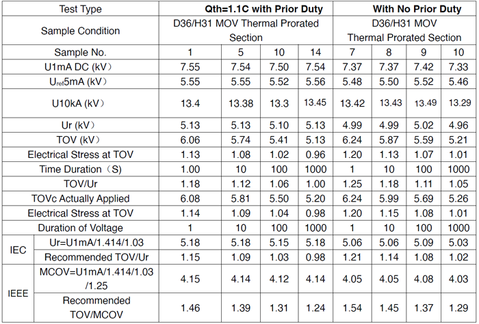
Samples #1, 2 and 3 (Ur=U1mA DC/(1.414*1.04), MCOV=0.8Ur, preheating temperature of 75°C, and 100 kA high current impulse) twice passed the operating duty test under these severe conditions. Sample #4 (Ur=U1mA DC/(1.414*1.0), MCOV=0.85Ur, preheating temperature of 75°C, 100 kA high current impulse) also twice passed the operating duty test under these severe conditions. Samples #5, 6, 7 and 8 (Ur=U1mA DC/(1.414*1.0), MCOV=0.85Ur, preheating temperature is 75°C, 100 kA high current impulse) passed the operating duty test once under the severe conditions.
It can therefore be inferred from these test results that when rated voltage Ur and MCOV of the arrester are selected according to the following conditions, the thermal prorated section is able to successfully pass the operating duty test specified in the standards, i.e.:
For IEC standard: Ur≤ U1mA DC /1.414=0.707U1mA DC
MCOV≤0.85Ur
Consider that for D36 MOV ,Uref 3mA=1.03* U1mA DC/1.414
Ur≤ Uref 3mA/1.03
For the IEEE standard: 1.25MCOV≤ U1mA DC /1.414
k=MCOV/Ur
k =0.81-0.85
Then, k*Ur*1.25≤ U1mA DC /1.414
Ur≤ (U1mA DC /1.414)/ (k*1.25)
Consider that for D36 MOV, Uref 3mA=1.03* U1mA DC /1.414
Ur≤ (Uref 3mA/1.03)/ (k*1.25)
If k=0.85
Ur≤ (U1mA DC /1.414)/ (0.85*1.25) =0.6654 U1mA DC
or Ur≤ (Uref 3mA/1.03)/(0.85*1.25) =0.914 Uref3mA

TOV Characteristics
Temporary overvoltage (TOV) time characteristic is the corresponding relationship between temporary overvoltage and time, which is of great significance for safe operation of an arrester. The test methods stipulated by the new IEC and IEEE standards are basically the same (see Fig. 7).
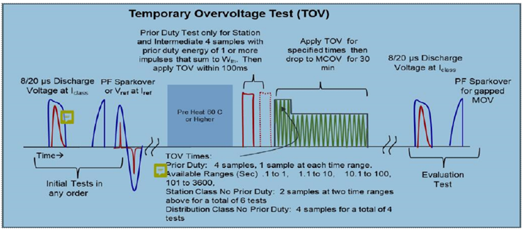
The TOV test contains a ‘with prior duty’ TOV test and a ‘no prior duty’ TOV test, although the IEEE standard does not require the prior duty TOV test.
TOV Performance with No Prior Duty
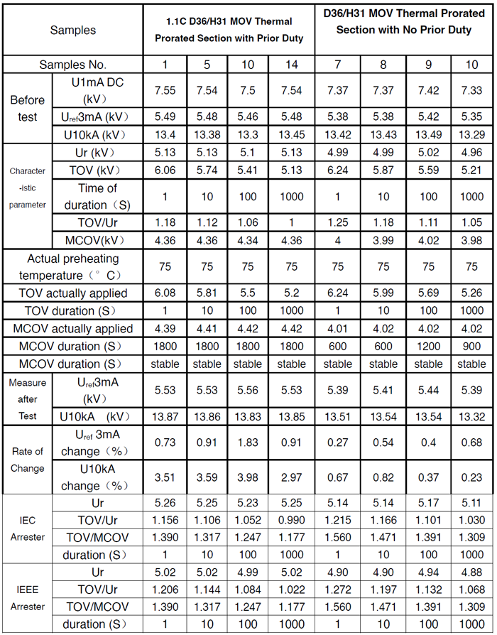
The TOV test with no prior duty was performed on the MOV thermal section and Table 7 outlines an extract of test results.
TOV with Prior Duty
The injection energy of the prior duty test was 8/20 µS lightning current and, to increase test severity, the charge was injected in two phases of 1.1C. Moreover, the preheating temperature of the section was also increased to 75°C. Test results are shown in Table 7.

Reference Voltage of Arrester
Based on performance of MOV as discussed above, the first issue is how to design arrester parameters according to IEC 60099-4:2014 and IEEE C62.11-2020. Usually, rated voltage and nominal discharge current of an arrester are clear. Therefore, the designer of arresters only needs to determine the following parameters:
• Residual voltage;
• AC reference voltage Uref or DC reference voltage U1mA DC;
• MOV specifications match;
• TOV characteristic verification.
Residual Voltage & Reference Voltage
For a specific MOV, residual voltage of MOV is closely related to reference voltage and reference voltage and residual voltage of each block are within a certain range. Also, the ratio Ures/Uref is within a certain range. Therefore, when reference voltage is determined, residual voltage is also in a certain range, and residual voltage can be controlled within a suitable range with a reasonable combination of MOV match or the fine control of reference voltage. The ratio of the voltage, Ua, to reference voltage Ua/Uref of the MOV/arrester subjected to various tests or operations can be considered as the electrical stress. When reference voltage is a certain value, the higher the applied voltage, Ua, the higher the electrical stress, the greater the current of the MOV arrester and the greater the energy absorbed. And vice versa. Under higher electrical stress, the test is harsher and more difficult it is to pass. Moreover, the higher the electrical stress of the arrester in operation, the higher the probability of damage due to accidents in operation.
IEC 60099-4:2014 and IEEE C62.11-2020 have similar provisions for the operating duty test. If the voltage 1.25MCOV applied for 10 seconds in IEEE C62.11-2020 is regarded as Ur, the test procedures and criteria of the two are almost identical. In the operating duty test, during the application of Ur, the electrical stress of the resistor is Ur/Uref. If Uref is taken as the DC reference voltage U1mA DC, the electrical stress is Ur*1.414/U1mA DC.
As mentioned, for arresters using IEC standards, the rated voltage Ur verified after the enhanced operating duty test is as follows:
Ur≤ U1mA DC/1.414
U1mA DC≥Ur*1.414
For D36 MOV, Uref3mA=1.03* U1mA DC/1.414
Ur≤ Uref3mA /1.03
Uref3mA≥1.03*Ur
MCOV=0.80Ur
This is the principle for determining minimum reference voltage of a lightning arrester with a rated voltage of Ur.
Since the test of clause 1.10 is stricter than the standard requirements, the corresponding electrical stress can be appropriately reduced, TGE recommends:
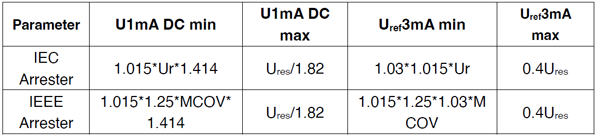
For IEC standards, U1mA DCmin=1.015*Ur*1.414 (formula 2.1-1)
or Uref3mAmin=1.03*1.015*Ur (formula 2.1-2)
Since the 10S voltage applied by IEEE C62.11-2020 is 1.25MCOV, therefore, for the heavy duty arrester of IEEE C62.11-2020:
U1mA DCmin=1.015*1.25*MCOV*1.414 (formula 2.1-3)
or Uref3mAmin =1.015*1.25*1.03*MCOV (formula 2.1-4)
The formula above gives the minimum reference voltage. Under this reference voltage, the corresponding operating duty test can pass reliable.
For heavy duty arresters specified in IEC 60099-4:2014 and IEEE C62.11-2020, the ratio of maximum value of the lightning residual voltage (Ures) at the nominal discharge current to the rated voltage (Ures/Ur) is generally 2.65-3.1 and 2.9-3.3, respectively.
For D36 MOV, Ures/U1mA DC=1.78-1.9, the median value in mass production is generally 1.815. Taking into account the mass production, the MOV of different residual voltage levels can be used together, and the median value of Ures/U1mA DC is determined to be 1.82. Therefore, for a lightning arrester with a specific rated voltage of Ur, the maximum reference voltage can be determined by the following formula:
U1mAmax=Ures/1.82 (formula 2.1-5)
Since Uref3mA=1.03*U1mA/1.414:
Uref3mAmax=0.4Ures (formula 2.1-6)
Table 8 shows the value rules at TGE for maximum and minimum reference voltage of arresters.
The formulas determine minimum and maximum reference voltage of the arrester respectively. The difference between maximum and minimum value is the tolerance range for matching the reference voltage of the MOV. Clearly, the higher the residual voltage and the larger the tolerance range, the less the difficulty of matching MOV. Subsequently, in mass production there could be a wide voltage range of MOV to use for matching. The smaller the residual voltage, the more difficult it will be to match.
Therefore, for arresters with low residual voltage, some MOVs taken from mass production will not meet requirements and cannot be used. This will increase production costs. On the other hand, if the residual voltage can meet the requirements, when the minimum reference voltage meets the requirements, the tolerance range of the determined reference voltage is appropriately reduced. Then, residual voltage of the whole batch of arresters will be reduced and dispersion of reference voltage will also be reduced. Conversely, if minimum reference voltage is properly increased when residual voltage meets requirements, electrical stress during arrester operation will be reduced and quantity of MOVs used will increase. This is conducive to improved operational reliability of the arrester although production cost of the arrester will increase. All these technical and economic factors need to be carefully considered by a designer.
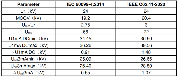
The following is an example of such an analysis at 24 kV:
Verification of TOV Performance
Since it is a very important technical parameter, TOV-time characteristic has a major influence on safe operation of lightning arresters. The structural characteristics and operating rules of a power grid will determine its temporary overvoltage characteristics. The arrester user will therefore have to verify the TOV-time characteristics of the arrester according to those of the grid to determine whether these can meet requirements. Only arresters meeting such requirements are safe in operation and will not fail due to overload when there is temporary overvoltage.
Therefore, according to the standards, manufacturers must publish the TOV-time characteristic and this should be verified by testing.
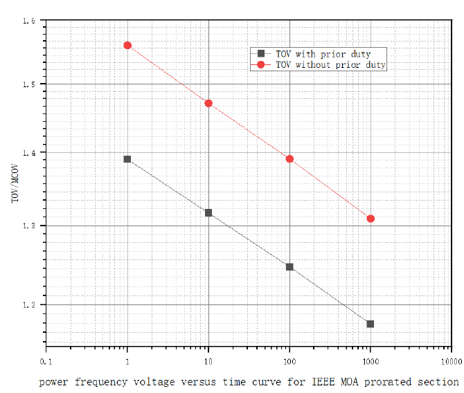
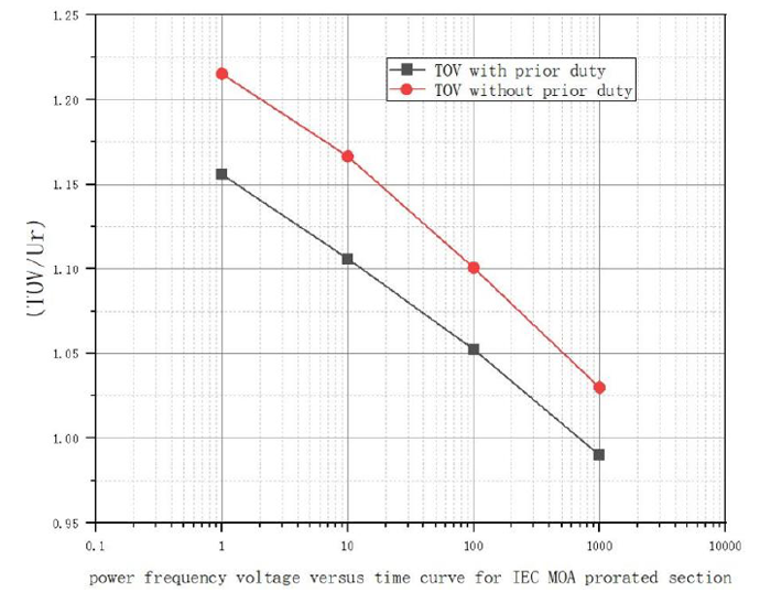
TOV tests were conducted on the thermal prorated section of the D36, both with no prior duty and with prior duty and results are summarized in Table 10.
Recommended values for TOV based on minimum reference voltage determined in Clause 2.1 are given in the table. If the TOV is higher than the recommended value, this does not mean that the test cannot be passed under this value. But due to the limited capacity of test equipment, verification of a higher TOV value could not be carried out in TGE’s own laboratory and TOV under 0.1S was not tested and verified.
In summary, for an arrester with a specific Ur, the reference voltage, residual voltage and TOV values interact once the MOV characteristics have been determined. If the residual voltage needs to be reduced, the reference voltage or the tolerance range of the reference voltage should be appropriately reduced and minimum reference voltage as well as TOV value are correspondingly reduced. And vice versa. In any excessive effort to reduce residual voltage, the arrester designer does not want to reduce the TOV value. In this way, the MOV has to be selected with a narrow voltage range. This could lead to some MOVs not being able to be used, resulting in increased production costs.

Conclusions
1. Results from many tests have demonstrated that the technical performance of the new glass coating D36 MOV meets the requirements of IEC 60099-4:2014, IEEE C62.11-2020 and GB 11032-2020. There is also a certain additional margin that can be used in manufacturing heavy-duty surge arrester specified according to these standards.
2. Relevant tests have confirmed that the D36 MOV also offers good stability, while meeting requirements of the relevant standards. This ensures safe and reliable long-term operation.
3. The above discussion presents the basic principles and design rules for heavy duty arresters whose rated voltage, reference voltage, residual voltage and frequency temporary overvoltage-time characteristics are matched. It also gives recommended methods as well as values.
Note: The samples used in the various tests above were from different batches of MOVs. There may therefore be slight variations in performance. Also, test methods may have small differences from the standards. Nonetheless, this test data will provide certain support for the arrester designer. It should also be noted that the analysis and recommendation are based on the author’s own experience and opinions. However, it is hoped that this analysis and recommendations can provide inspiration for users of MOVs, who can design optimized arresters with these new MOVs according to their own tests and experience.