Hydro One owns most of the transmission grid in Canada’s province of Ontario, with main corridors at 500 kV and 230 kV as well as regionally at 115 kV. Overvoltages on this network occur in a wide variety of waveforms and situations and, while metal oxide surge arresters provide protection in most applications, spark gaps of various designs are also required. Moreover, some voltage transients are controlled with capacitors and even shunt reactors. Hydro One’s surge environment and application philosophy puts comparatively little emphasis on surge arresters and therefore these tend to last many years. As a result, the utility’s arrester population has a fairly broad technological diversity, with service life determined mostly by factors such as integrity of housings.
This edited past contribution to INMR by Jody Levine, Senior Network Management Engineer, explained Hydro One Network’s approach to overvoltage protection as well as various mitigation strategies employed – from routine to creative. Surge arrester replacement strategy, inspection and failure analysis are also discussed and failures of special interest are presented.
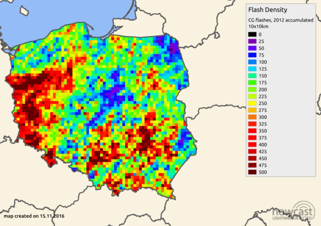
Ontario has relatively modest lightning exposure compared to the rest of North America, with only isolated ‘hot’ spots such as the agricultural south that receives over 8 flashes/km2/year. By contrast, the vast rocky north sees less than one flash/km2/year. For example, surge counters installed on a transformer connected to 160 km of 230 kV line some 50 km from the eastern shore of Lake Superior recorded only 20 events over a period of 14 years. This is consistent with historical lightning exposure.
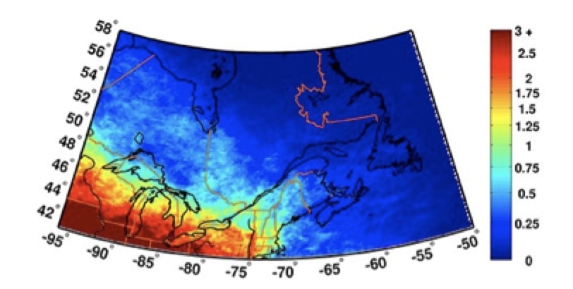
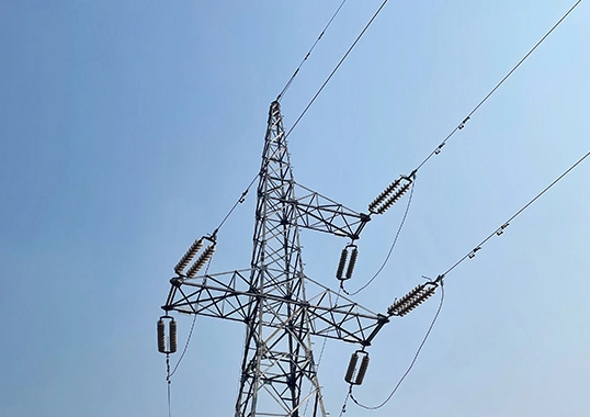
Hydro One employs shield wires on its transmission lines but poor footing resistance in the rocky terrain of the north means that lightning is still a nuisance over these long transmission distances. There have been efforts to apply line surge arresters but the large numbers of towers as well as problems with mechanical durability of connections reduced interest in this solution. At substations, surge arresters are typically applied both to transformers and HV circuit breakers. Most stations are also equipped with lightning masts. Switching surge is only a concern at 500 kV, particularly where there are no tap-off stations on long segments of line to drain charge. These transients are mostly mitigated by means of breaker closing resistors and point-on-wave pole control.
Hydro One’s surge arrester applications are slightly less stringent than recommended in IEEE C62.22 and the consequence of this philosophy is that their energy wear on the system is extremely rare. Table 1 shows typical arrester ratings.

Cases of Overvoltage Protection
Temporary Overvoltage on 115 kV Urban Line
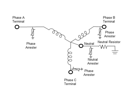
The 500 kV and 230 kV networks are effectively grounded yet there are still special situations on the transmission system where temporary overvoltage (TOV) duty is beyond the capability of metal oxide varistors. Since large municipal distribution systems are run as effectively grounded, dual element spot networks, step-down transformers have dual secondary windings. To reduce harmonics and limit HV fault current, transformer winding configurations must be either delta-wye-wye or wye-zigzag-zigzag.
Distribution utilities that are Hydro One customers require separate voltage regulation on the two secondary windings and prefer not to manage the phase shift that would accompany tap changes on half a zigzag, thereby limiting transformer configuration to delta primaries. In congested city cores, the high-voltage conductors supplying primary windings are underground cables. The result is that the inductance of the non-effectively grounded delta windings and the large cable capacitance experience partial resonance when the transformer back-feeds into a line-to-ground fault. In such cases, TOV levels can exceed three per unit. At these stations, the primary function of overvoltage protection is to limit TOV, not surges. Since this cannot be achieved with a gapless surge arrester, rod gaps continue to be employed instead (see Fig. 2).
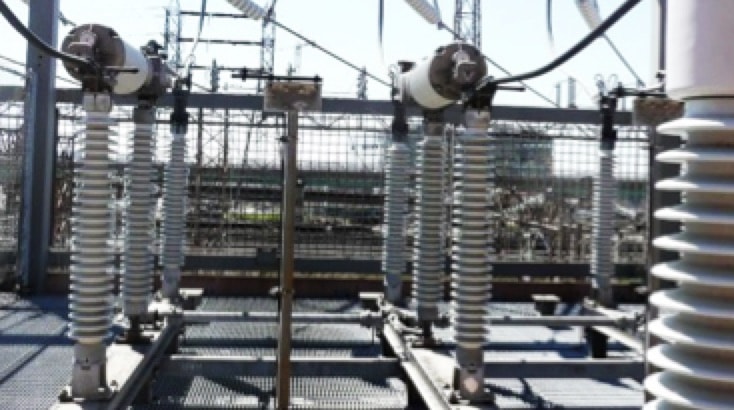
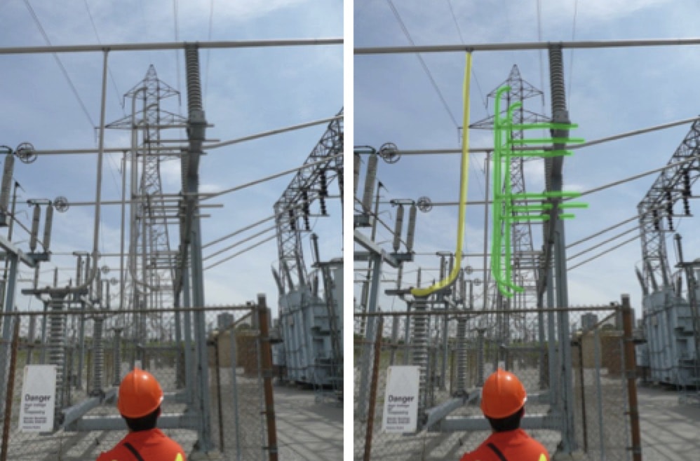
A major disadvantage of gaps is that they are not self-clearing and they can also have unsatisfactory steep front surge response characteristics. Pipe gaps (as in Fig. 3) were developed by Ontario Hydro during the 1960s for improved steep front performance. The high effective area increases pre-strike current and reduces time to sparkover on fast-rise surges. This geometry has more uniform field distribution compared to a rod gap, giving it higher AC withstand. As such, the rod gap is still required for TOV protection. Instead of gaps, 115 kV shunt reactors were employed at one station to shift the cable and transformer winding combination off resonance and reduce TOV to a more manageable level.
High-Voltage Cable Sheath Voltage Limiters
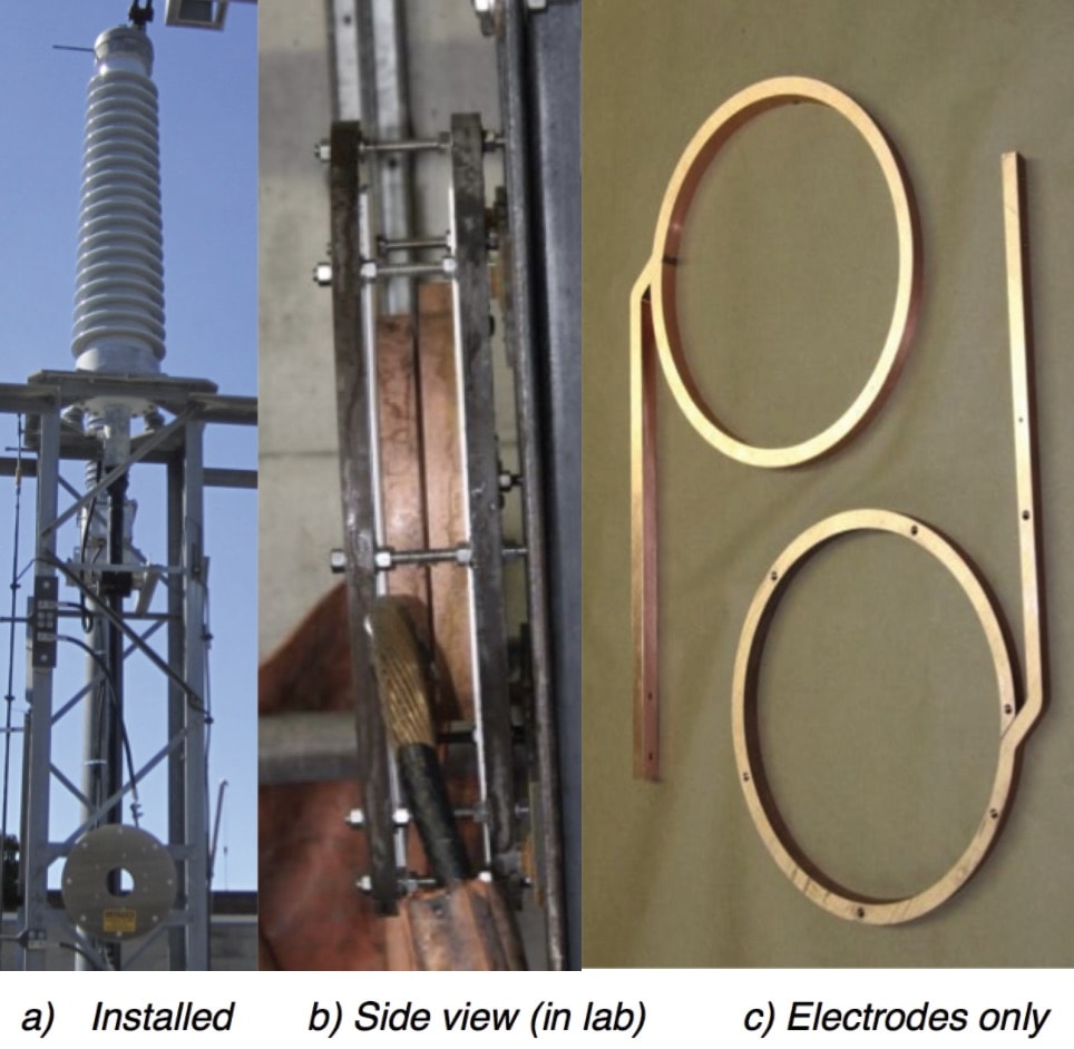
Cable sheath voltage limiters are another specialized application. These require a low protective level for the thin jacket insulation and must be able to carry large AC return currents in the event of a fault on the circuit. Induced AC voltages during faults can result in loss of coordination for gapless zinc-oxide surge arresters. A simple rod gap is problematic at low voltages because a small amount of erosion can cause unacceptable increase in protective level. Ontario Hydro’s solution was a ring gap, where ring-shaped electrodes are mounted parallel to each other across a 2.5 mm gap to achieve sparkover voltage below 10 kV (see Fig. 4). A commutation gap in the ring causes the arc to be pushed away from the supply point and to circulate around the ring, thereby reducing electrode erosion. The latest version of these can withstand 70 kA for 0.25 seconds.
Controlling Rate of Rise of Transient Recovery Voltage (TRV) for Capacitor Bank Breakers with Current Limiting Reactors
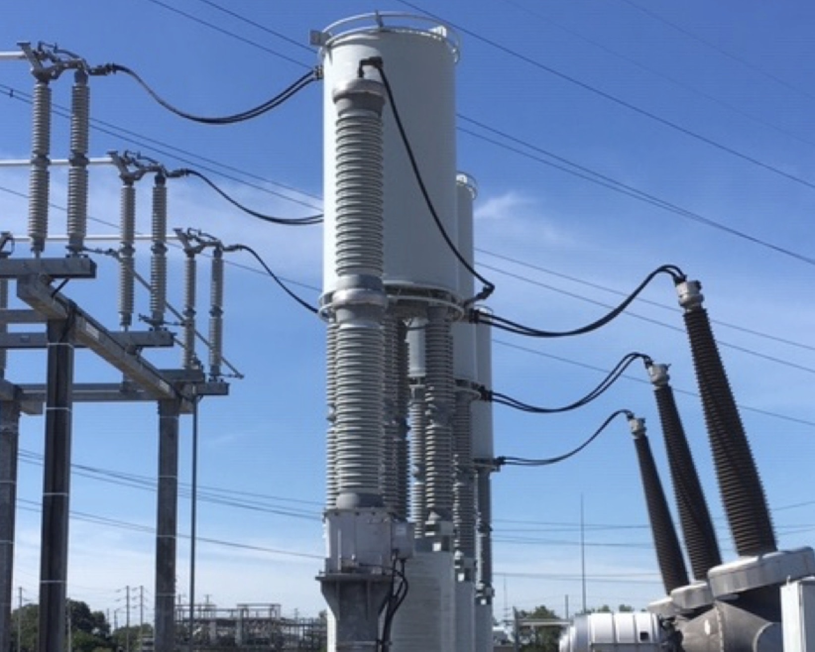
In the case of circuit breaker interruption, it is not only voltage peak but also rate of rise of voltage that must be controlled. In 2007, Hydro One had a spectacular event where a combination of surface contamination and mounting configuration of a 230 kV ungrounded capacitor bank led to a complete phase-to-phase fault. Although the capacitor bank was protected by two 345 kV breakers in series, they were not fast enough to beat the rate-of-rise of recovery voltage due to the high fault current passing through the inrush-limiting series reactor. Both breakers were destroyed. Following this, all large capacitor banks had their reactors bypassed while these were fitted with additional capacitors to protect the breaker. Capacitive voltage transformers were installed for this purpose. Some are shunt-connected between reactor and breaker (see Fig. 5) while others across the reactor.
Series Capacitor Protection
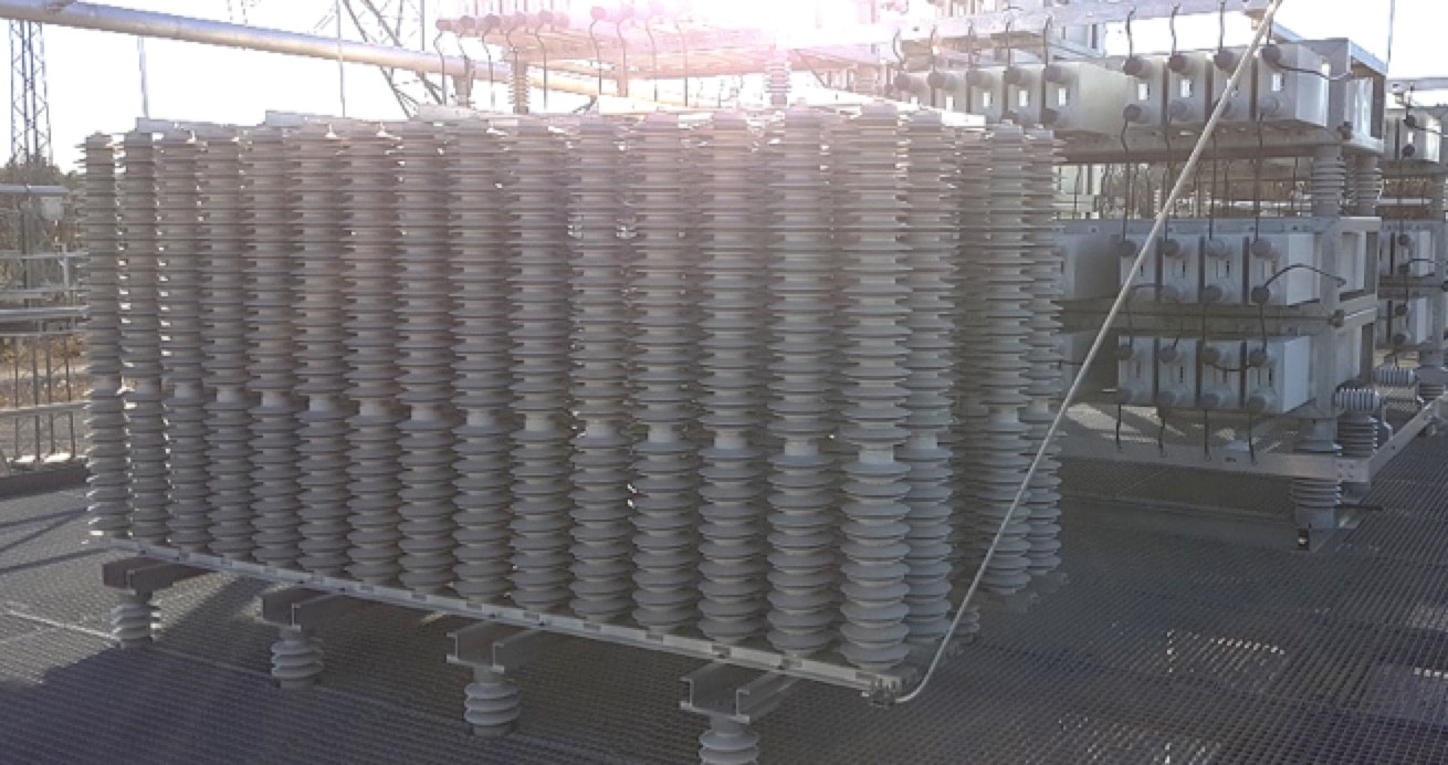
Some capacitors require their own protection. For example, Hydro One has a VAr-compensating series capacitor at the mid point of a 300 km section of 500 kV line. The capacitor is protected from through faults by a triggered gap serving as fast bypass. But that is not enough and surge arresters are still required to carry some of the current. As expected, the surge arrester in this case is a large, multi-column arrangement (see Fig. 6).
Surge Arrester Fleet
Hydro One has a population of about 7000 surge arresters, applied mostly to transformers and circuit breakers. Some 3000 of these are known to be polymer-housed, gapless, zinc-oxide type while some 1000 are porcelain-housed, gapless, zinc-oxide type. About 500 are porcelain-housed, gapped, silicon-carbide type and the remaining 2500 have insufficient data in the registry to indicate what type they are. The basic asset strategy employs minimal condition assessment combined with targeted replacement only for those deemed to pose the greatest hazard, namely the old silicon-carbide units.
Maintenance
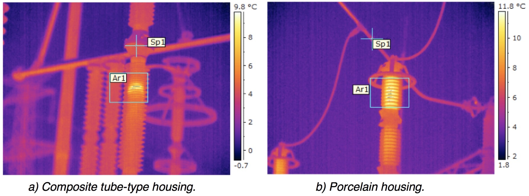
Since surge arresters have no maintainable components, maintenance activities are limited to inspection and most units are run until failure. Up to 20 years ago, standard installation practice saw arresters placed on standoff insulators with the idea that surge counters or leakage current monitors might then be applied. But there were never enough arrester failures to justify such measures and in fact failure of the standoff insulators themselves was more common. All newer installations therefore have the surge arrester mounted directly on the steel structure and standoff insulators are removed from old structures whenever arresters are replaced. An insulated ground lead is still used to avoid arcing between conductor and structure. Surge arresters are included in routine thermographic inspection of stations and a few pre-failure units have been identified. Fig. 7 shows examples of abnormal heating and arresters with such heat signatures are typically replaced in anticipation that they could soon fail.
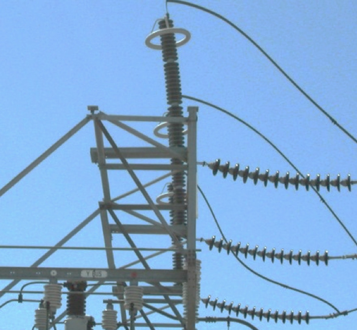
Regular visual inspection of arresters is also used to identify issues such as cracked porcelain housings, broken grading rings and blown disconnectors (where employed). Fig. 8 shows an incident where moulded surge arresters were bent during a windstorm.
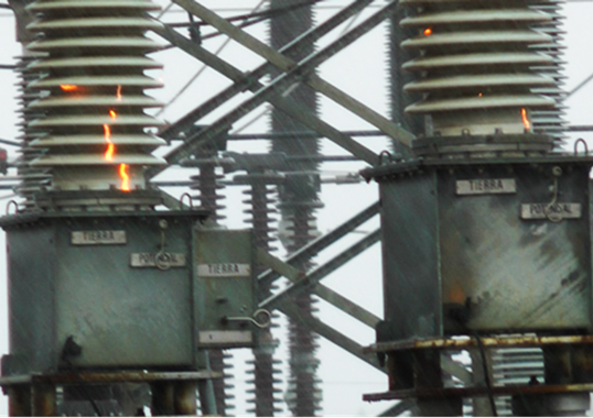
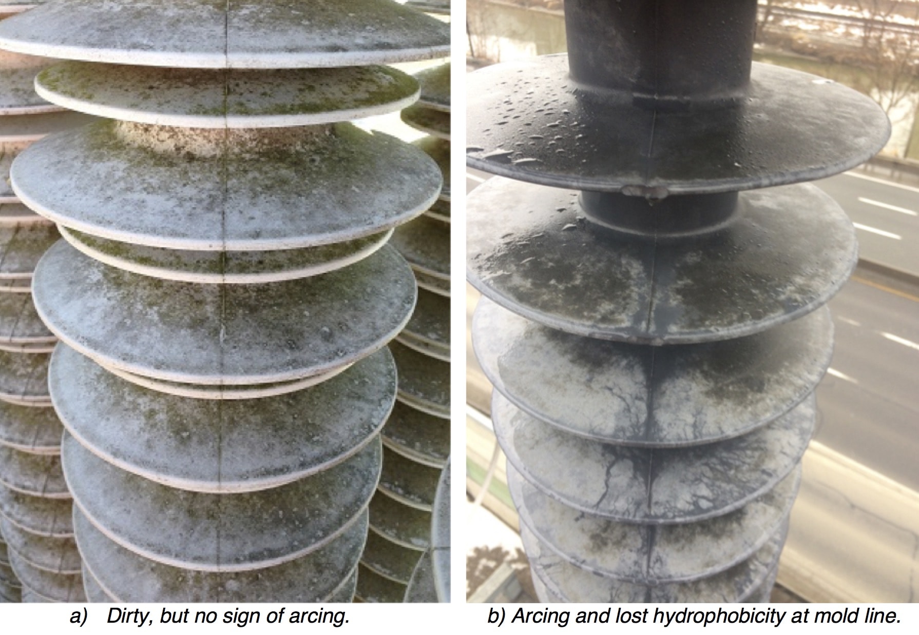
Surface contamination is a problem for arresters at certain stations. Pollution should not affect performance of those equipped with silicone housings so long as these remain hydrophobic. By contrast, evidence of arcing activity and loss of hydrophobicity signal onset of housing degradation. Such arresters have to be checked periodically for evidence of erosion and, if necessary, replaced (as in Fig. 9).
Failures
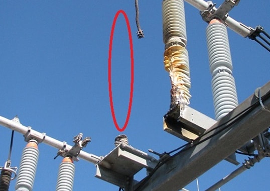
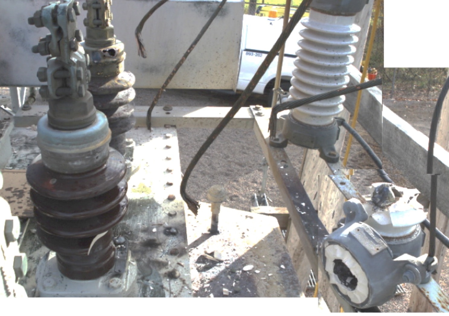
In general, the arrester population has been highly reliable with only isolated failures recorded each year. Hydro One maintains good spares coverage in a central warehouse to assure fast restoration time in such cases. Nevertheless, there is still concern, particularly in regard to older porcelain-housed units with inadequate pressure relief. These represent a safety hazard to personnel as well as to adjacent equipment, as in the example shown in Fig. 10.
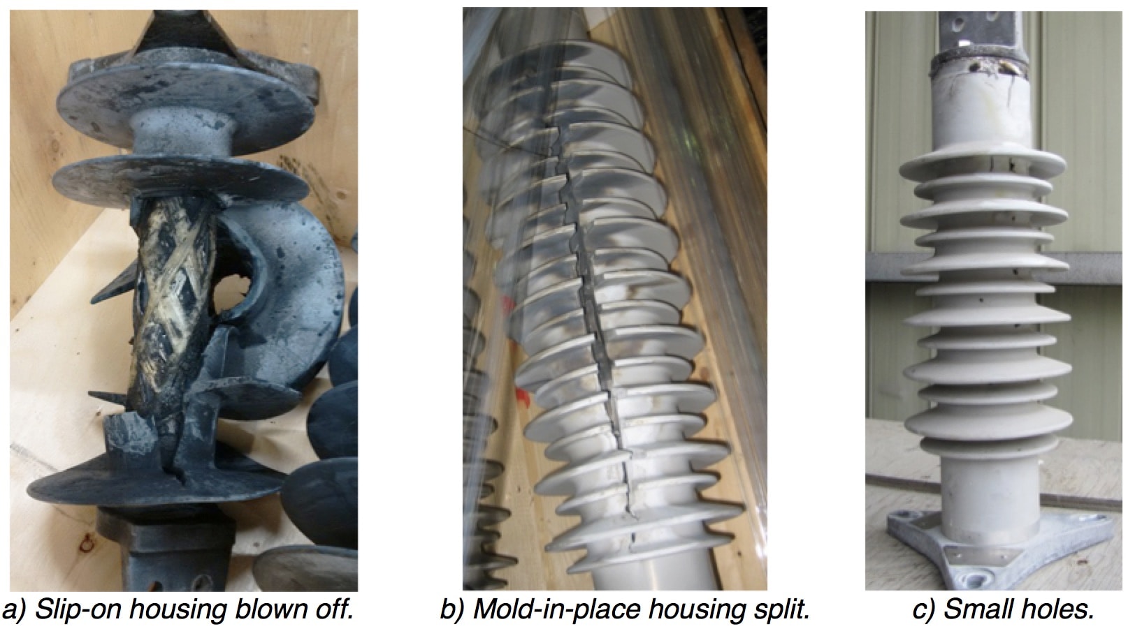
Hydro One has had no documented explosions of porcelain-housed arresters equipped with vent ports, although one failure of a 500 kV unit damaged the housing enough to cause large pieces to fall to the ground. Although this is permitted in IEEE C62.11 short circuit testing, Hydro One considers the safety risk to be sufficiently high that porcelain-housed arresters have not been approved for purchase since 2004. Polymer-housed arresters, by contrast, tend to vent safely and do not expel or drop zinc-oxide blocks or any other sharp heavy pieces that could injure personnel or damage nearby equipment. Tube-type composite housings typically have similar pressure relief behavior to modern porcelain arresters, which vent with no damage to the housing. But unlike porcelain, composite housings resist cracking and breakage from thermal shock. Molded housings tend to simply split and allow gas to escape. Where fault currents are low and protection is fast, such vent holes may be so small that the failure is difficult to see from the ground (see Fig. 11).
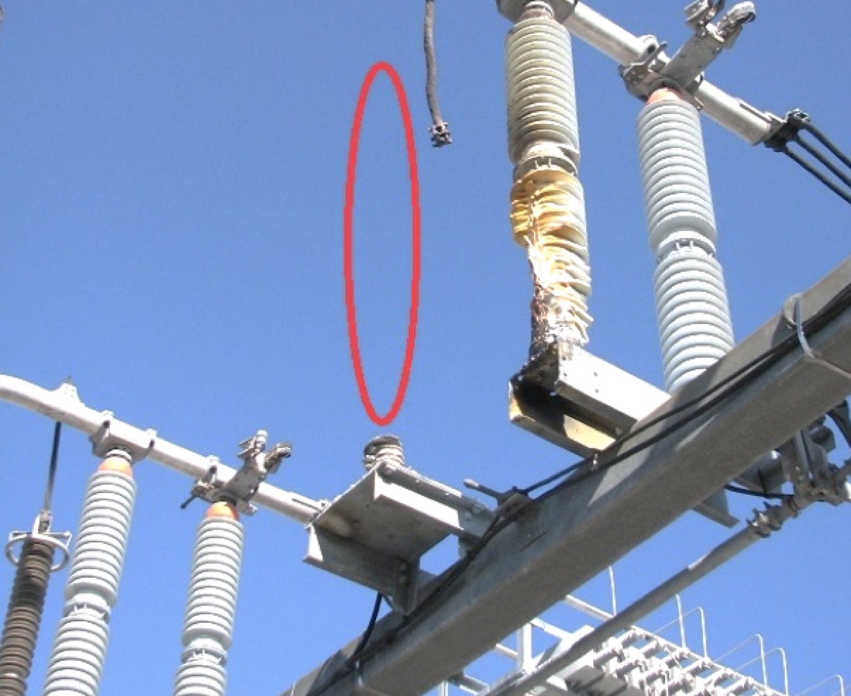
There are limits to the mechanical withstand of polymeric housings. The IEEE C62.11 short-circuit test follows a protocol that simulates a typical arrester fault as a result of a surge or short-time TOV event. The test does not simulate a fault that occurs very slowly, e.g. over minutes or hours. This can cause the arrester to become very hot over a long period of time and thereby weaken its structure. In fact, Hydro One recorded two events in which a molded surge arrester fragmented severely. One involved an undetected line fault on an ungrounded transformer winding that did not have a surge arrester rated for the line-to-line voltage. Another was on a circuit breaker for a large 230 kV capacitor bank, where one breaker pole remained stuck closed upon de-energization. This caused the AC voltage from the stuck phase to be superimposed onto the remaining DC charge on another phase, which slowly discharged through the arrester. The arrester was so hot at time of failure that no fragments could be found for forensic examination (see Fig. 12).
Failure Analysis
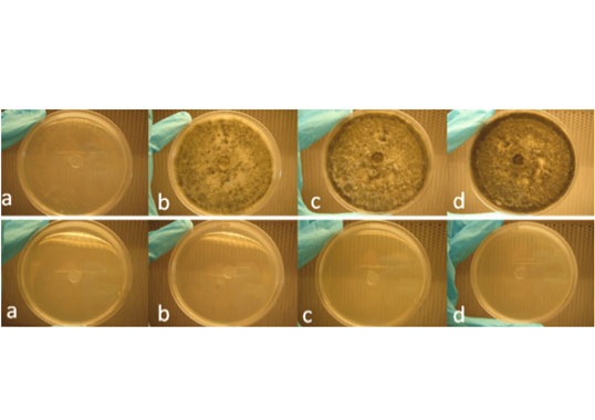
Hydro One conducts failure analysis on surge arresters that suffer faults well before end of normal expected service life yet without any obvious overstress. The purpose of such dissection is to determine whether the problem was related to a manufacturing defect or some unexpected system condition that caused excessive energy duty. This will indicate whether simple replacement is appropriate or if a change of rating is necessary. It will also help determine whether another component may have caused the condition or if some other defect needs to be addressed. Zinc oxide varistor blocks inherently control overvoltage internally and flashover only in the presence of extremely high surge currents (e.g. greater than 100 kA) or due to high radial electric fields (e.g. from contaminated housing) or nearby arcing from other blocks. Arrester failure is rarely simply an internal or external flashover.
Energy failure results from overheating that causes blocks to puncture, with obvious fault paths on the inside as well as cracking from the inside out. Housing failure, by contrast, allows moisture ingress, which causes electrical tracking of an internal component – whether the surface of the blocks, the fiberglass structure or other housing material. Fig. 13 shows examples of different types of failed blocks.
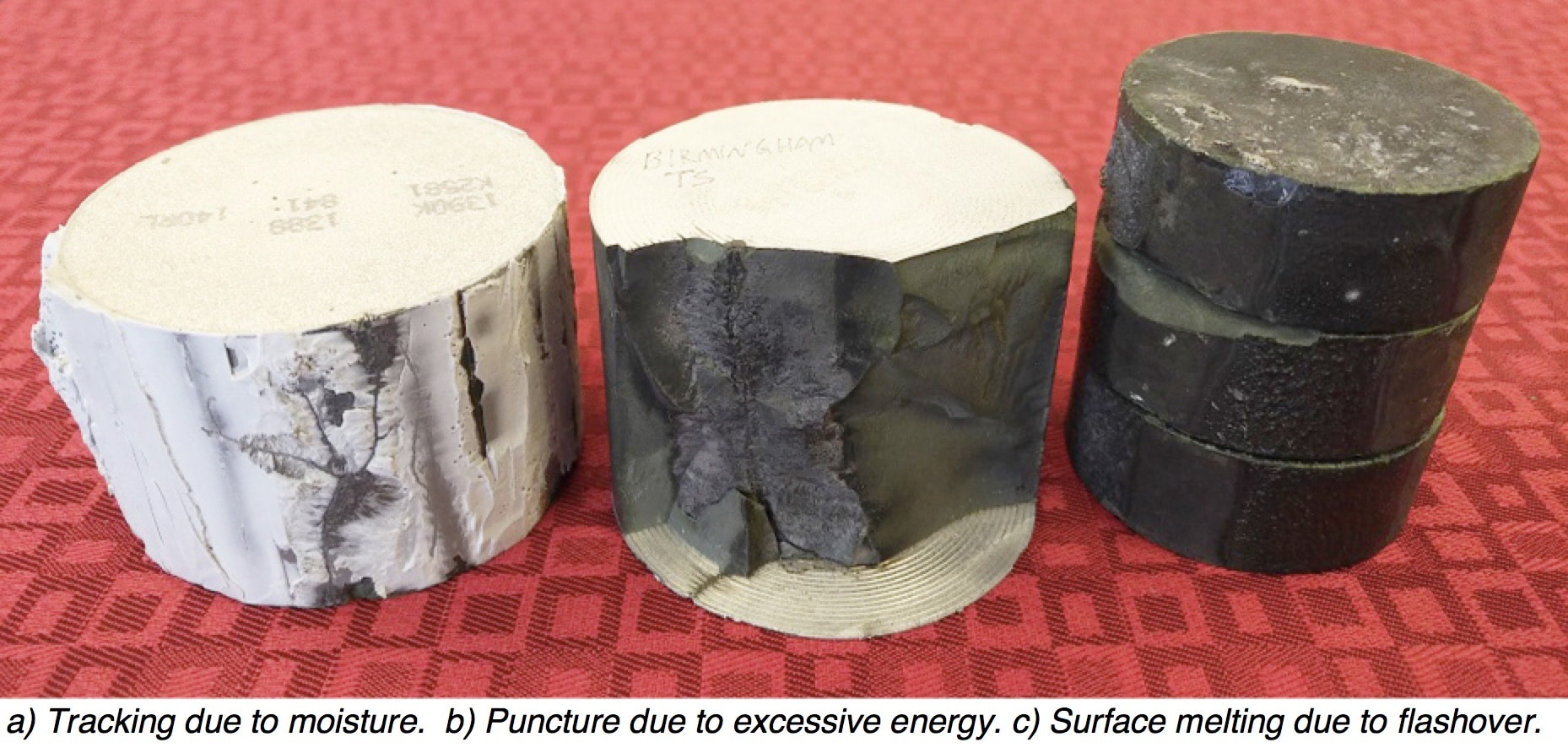
Tracking always progresses to flashover along the tracked blocks, often destroying the track due to surface melting. Moreover, at least some of the remaining blocks in the section suffer energy failure due to overvoltage from having the tracked blocks shorted for a period of time. Any evidence of tracking is a sign of internal contamination, no matter how many other blocks exhibit failure from excessive energy. A pure energy failure could have a combination of punctured/cracked blocks and some that show only surface flashover. Even if the arrester structure remains intact, these types of failures typically show other evidence of excessive heat, such as distortion of components not directly in the path of the arc or loss of adhesion to the housing.
In cases where there is no evidence of tracking on any component and there is a combination of blocks that have suffered excessive energy and surface flashover, either scenario may be possible. The failure may have started with tracking but the track was melted by the surface flashover. Or it could be an energy failure where puncture of several blocks created enough ionized gas to flash over other blocks. Other indicators may then be needed to establish likely root cause.
Summary
Hydro One’s network has comparatively modest lightning exposure and employs a variety of devices to control overvoltages, including some unusual gap devices. Surge arresters fail only infrequently and thus require no specific maintenance. Only units that present an explosion hazard are targeted for replacement. Some failures have occurred under unusual circumstances and failure analysis is conducted whenever root cause is not clear.
References
1. Environment Canada, Average Flash Density for Eastern Canada (1999 to 2013) URL: https://www.canada.ca/en/environment-climate-change/services/lightning/statistics/maps-hotspots.html
2. IEEE C62.22-2009, IEEE Guide for the Application for Metal-Oxide Surge Arresters for Alternating Current Systems
3. Lishchyna, L., “Lightning Protection of 230-kV Stations by Pipe Gaps,” IEEE Transactions on Power Apparatus and Systems, PAS-87, No.1, January 1968
4. IEEE C62.11-2005, IEEE Standard for Metal-Oxide Surge Arresters for AC Power Circuits (>1 kV)

