This edited contribution by Jeff Butler of Hubbell Power Systems at the 2023 INMR WORLD CONGRESS in Bangkok discusses application of polymeric insulator technology when HVDC transmission is selected as the most effective solution for a new line. He explains that the benefits of such lines are only enhanced with the combination of efficiency and durability provided by the latest generation of high voltage polymeric insulators.
HVDC Transmission: Considerations for Insulator Selection
This focus of this article begins once a decision has been made to pursue design of an HVDC transmission line. It therefore avoids discussion of the relative advantages of AC and DC technologies and instead presents some key topics that should be explored concerning the role that polymer insulators can play to support the development of an HVDC project.
Selection of the insulators for HVDC transmission lines differs slightly from the approach for HVAC transmission lines. The focus will be on key considerations around understanding the impact that the unique conditions of phase voltage and polarity of the line have on the insulator selection. These challenges are not insurmountable, but particular consideration must be taken to make sure they are properly addressed.
HVDC Transmission Line: Phase Voltage (Part 1)
There are different impacts between HVDC and HVAC that the determined system voltage of a line has on selection of proper insulator. For example, in the case of HVDC applications, peak voltage is constant, unlike the peak voltage of an HVAC application. This peak voltage then plays a critical role in defining the electrical environment for the insulators. Specifically, peak voltage affects electric field and applicable shielding required for the line to eliminate visual corona, reduce RIV to acceptable levels, and protect the polymeric insulator.
To illustrate, the example of two high voltage transmission lines will be used. Both lines are set at 600 kV system voltage: one a 600 kV HVAC line, the other a ±600 kV HVDC line. The voltage curves vary significantly even though they are both rated at 600 kV (see Fig. 1). The difference in peak voltages plays an important role in the design of proper shielding and corona considerations for both hardware and insulator assemblies.
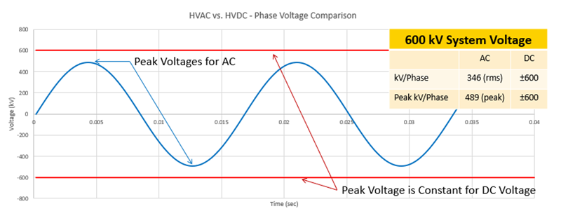
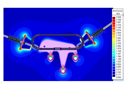
Whether evaluating potential behavior of an assembly using a simulated software-based program or performing full scale corona/RIV tests in a laboratory, it is important to understand the peak voltage the assembly will experience. Due to this peak voltage difference between HVAC and HVDC, there will be a need for additional evaluation of the assembly shielding that is required to meet the desired corona and RIV thresholds of the line. Special attention should be taken to the electric field at the critical sealing interfaces of the polymer insulators. This special attention reduces the risk of exposure to higher e-field gradients that can result in pre-mature damage to the insulators. The availability of various corona and shielding ring options have successfully served to meet the corona and RIV requirements for HVDC transmission lines for polymer insulators for many decades. With a careful approach and attention to the proper consideration to address these shielding requirements at the peak voltage of the HVDC lines, polymer insulators will function very effectively for the decades of expected service life.

HVDC Transmission Line: Polarity
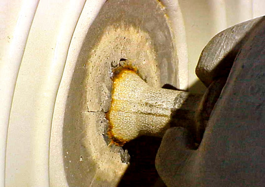
Another aspect of HVDC transmission lines that differs significantly from HVAC is the line polarity. Unlike the continuously varying polarity of HVAC lines, the constant polarity of HVDC lines presents unique challenges that must be taken into consideration through effective insulator selection and design. The ever-present challenge of corrosion that all outdoor materials must combat is further compounded by the nature of HVDC transmission lines. A brief discussion on the unique corrosion conditions of insulators will help lay a foundational understanding. For typical high voltage applications, there is the normally occurring ferrous corrosion combined with the effects of the electrical phenomenon that tends to develop on the surface of insulators as a contamination layer forms. When moisture is present, the leakage currents flow through the layers of wet contaminant and heating causes dry bands to form. These dry bands first form at the area of highest current density. Arcing that forms across these dry bands generates corrosive by-products such as ozone (O3), nitrous oxide gases (NOx) and nitric acid. In an insulator, the area of most severe corrosion occurs within the string with the end units experiencing less corrosion. It has also been observed that corrosion is more severe in deep-shell fog type insulators than in standard profile. These effects can all be explained by the ability, or lack thereof, for the insulator to vent these generated corrosive components. Both ozone and nitrous oxides are heavier than air, so for horizontal strings and line end units have the assistance of gravity to dissipate these gases so they don’t accumulate. Furthermore, air movement can help to dissipate these gases and assist in drying the contaminant layer. However, the influence of wind is most effective for shallow geometry where the air can more easily pass across the surface. In addition to these concerns present on all transmission lines, the particular design of HVDC transmission combines electrolytic corrosion as well. This way, the polarity of the poles contributes to the sacrifice of the positive electrode in the corrosion circuit.
Polymer insulators are well designed to combat the adverse corrosive conditions of HVDC applications. The natural hydrophobic property of the silicone rubber housing helps prevent the buildup of the contaminant layer. However, if a sufficient layer were to accumulate and leakage currents begin to flow across the wet contaminant layer, the relatively small diameter of the shank leads to high current density that quickly dries the insulator core thus reducing leakage currents. Furthermore, the inherent aerodynamic profile of the polymer sheds allows for effective gas dispersal across their surface as the open shed profile allows for effective natural washing from wind or rain to further reduce the buildup of contaminants on the surface. As noted, the highest metallic corrosive effect was not at the extreme ends of the insulator strings, thus the two metal end fittings at the extremes of the polymer insulator are less susceptible to the most severe corrosive activity. In addition to their protected location, the design of the larger diameter forged steel end fittings provides increased resistance to metallic corrosion to maintain the mechanical strength of the insulator string. If further corrosive protection of the end fittings is desired, there are optional considerations that could be considered such as additional zinc or the enhanced performance of Thermal Diffusion Galvanizing (TDG) over traditional HDG processes.
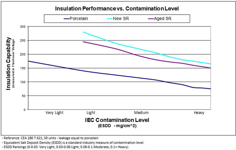
The constant polarity of the HVDC lines results in increased contamination build-up behavior, unlike that present on HVAC lines. The properties of both the material and the design of polymer insulators make them well-suited to address this challenge as well. The silicone rubber housing of polymer insulators makes them effective in reducing the likelihood of contamination build up that could lead to flashovers (see Fig. 3). For example, with the equivalent leakage distance to porcelain, the silicone rubber housing on the polymer insulators demonstrated significantly higher flashover voltages compared to porcelain from light to heavy contamination. This is due in part to the silicone rubber material but also a result of the geometry of the polymer insulator design to increase ohmic heating at the smaller diameter shank of the insulator. This heating dries the contaminant layer quicker and reduces leakage currents. Reducing leakage currents decreases probability of flashovers and consequently possible line operations and outages.
HVDC Transmission Line: Phase Voltage (Part 2)
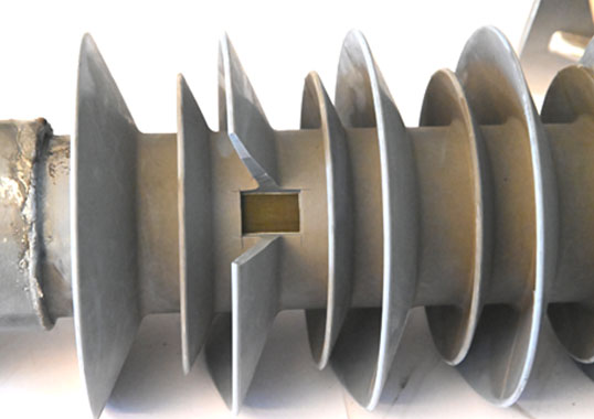
Returning to the topic of flashovers, the impact of phase voltage on flashover voltage means that certain criteria must be considered for HVDC applications. Two of the critical properties of any insulators are the strike or dry arc distance and leakage distance (Fig. 4). Using an example project at 600 kV system voltage, a comparison will be made between insulator selection and design options.

Case Study: 600 kV System Voltage (600 kV HVAC, ±600 kV HVDC)
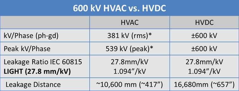
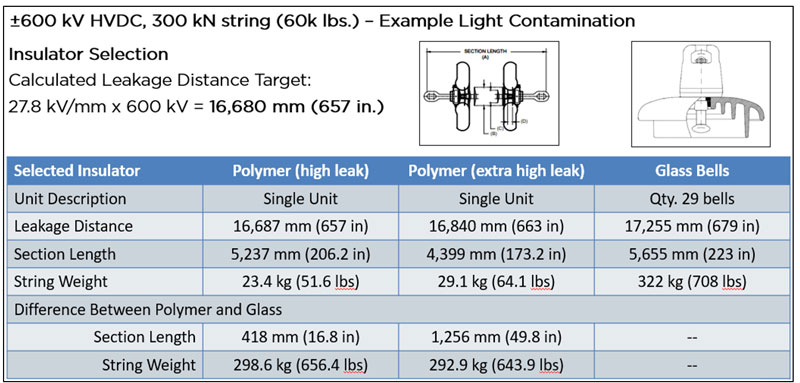
As discussed above, the critical voltage values for the insulator selection must be defined (see Table 1). Determining the peak voltage is then used for calculating the leakage distance requirements based on the site severity per IEC 60815. In this instance, the site severity was chosen as “Light” with a leakage distance ratio of 27.8 mm/kV. Thus, based on the determined peak voltages, the leakage distances are determined. As discussed, the HVDC line has higher peak voltage and consequently would also have a higher leakage distance requirement of ~60%. However, design considerations are a delicate balance between providing sufficient aerodynamic access to dissipate the harmful effects of the electrical activity while also meeting the increased leakage distance requirements of the HVDC system voltage. A possible polymeric insulator design was selected to meet that leakage distance requirement as well as performing a similar exercise for glass bell insulators to compare two possible design options (see Fig. 5). Both insulator strings meet the minimum leakage distance. The resulting section lengths and weights of the strings are also compared. In this case, the glass string required a total of 29 bells to meet the leakage distance. This resulted in an insulator string that was 418 mm (16.6 in.) longer and weighed 298.5 kg (656.6 lbs.) more than the comparable polymeric insulator. Further evaluation of the electrical characteristics required by the line is needed before the final design of the insulator string is determined, but this example demonstrates the effectiveness of the polymeric design to provide a range of leakage distances over a given section length.
Polymeric Insulators for HVDC: Further Considerations
With sufficient understanding of the nuances specific to HVDC applications, the opportunities polymer insulators can provide creates further exploration of project impact. Design options for shed profiles of polymer insulators provide increased efficiency of leakage distance over length. In the example referenced above for the 600 kV HVDC line, increased shed profile designs can significantly reduce insulator length. This provides opportunities to also optimize structure design to reduce tower heights, phase spacing, and consequently steel while still maintaining appropriate clearances. Reduced steel and reduced weight can lead to optimized foundation designs. These optimized towers and foundations can lead to reduced tower footprints and thus reduced clearance requirements for the transmission line right-of-way. All these opportunities can combine to achieve significant reduction in the costs of material, labor and land impact on the financial investment needed for the line.
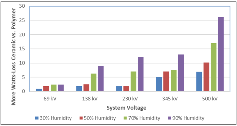
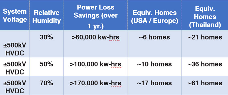
From an operational standpoint, an optimized polymeric insulator design has demonstrated significant improvements in power losses compared to conventional insulator materials. As humidity increases, leakage currents on the surfaces of insulators increase. However, the optimized geometry of polymeric insulators improves performance relative to the power losses associated with operation of high voltage transmission lines. A comparison was made using an equivalent ±500 kV HVDC line with 2,500 structures over 580 miles (933 km), 2 insulator strings per pole and 2 poles per structure. Based on the results of laboratory testing, power losses were significantly lower using polymeric insulators depending on humidity in the environment of the installed line (see Table 2).
Returning to the comparison of insulator strings to meet the leakage distance requirements (see Fig. 5). The weight savings of the insulator materials can greatly reduce labor and transportation costs. For example, per the United Kingdom’s guidelines provided by the Health and Safety Executive, it is recommended that the average person can safely handle 25 kg (55 lbs). Given this assumption and the design of the insulator string, Table 3 shows the significant difference in manual transportation details for each type of insulator string.

Polymeric Insulators for HVDC: Summary
Optimization opportunities using polymeric insulator designs can provide significant impact to a project. However, it is important to evaluate these possibilities early in the project life cycle. Early implementation or consideration of optimization opportunities for polymeric insulators provides the greatest effectiveness to overall project improvement in terms of performance and cost.
It is critical to understand the impact of peak voltage and polarity on the insulator assembly design. The impact of the HVDC voltage on contamination, corrosion, and resulting insulator design is important and can be effectively addressed. It is important to involve those who can provide the critical information and guidance needed in these important design decisions.
One of the main challenges today in evaluating polymeric insulators as an option for HVDC projects is based on the lack of available standards. There are limited applicable standards whether IEC, ANSI, IEEE, etc. There is some industry guidance available from organizations such as CIGRE. Part of this lack of product specific standards is based on the successful implementation of polymeric insulators in HVDC designs. Unlike the challenges faced by other insulator materials within the HVDC environment that have resulted in the need for specific standards to thoroughly prove the extensive requirements for this challenging application. High quality polymeric insulators have proven effective for decades in the challenging conditions discussed above. The material and design of these insulators creates advantages to the unique conditions of HVDC transmission lines.
There is increased consideration of HVDC transmission lines as an effective solution to meet the challenging demands of the global grid. The future of the global grid will depend upon proper evaluation and implementation of these optimal technologies and that includes properly understanding the impact of polymeric insulators on HVDC applications.

