Application of surge protection devices (metal oxide (MO) arresters) is essential for the safe operation of power systems. This edited contribution to INMR by Ralf Beuting as well as experts at Siemens Energy in Germany explains how targeted use of MO arresters, taking insulation coordination into account, permits lower insulation levels on individual components than usually requested. Lower insulation levels can then lead to cost reductions or open the door to new applications of existing designs.


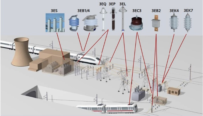
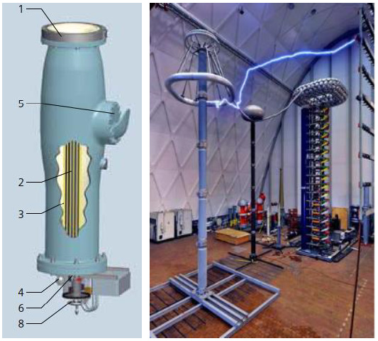
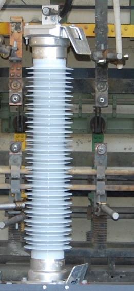
Surge arresters ensure the safe operation of energy systems and must be designed and installed in such a way that they safely control the magnitude of overvoltages at the connections of the devices being protected. These days, it can be stated that metal oxide (MO) arresters are state-of-the-art and characterized by high reliability. Various arrester designs and typical applications are shown in Fig. 1.
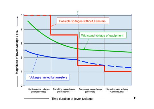
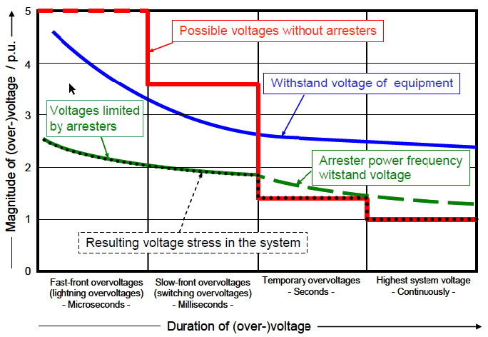
Depending on magnitude of the voltage that occurs, a basic distinction can be made between two working areas of a MO arrester. In the case of continuous voltages and temporary overvoltages, the device must guarantee operational stability, i.e. it must not be overloaded. In the second working range, the protection level of the arrester limits any overvoltages that occur. This is illustrated in Fig. 2.
In addition to the voltages that occur, the protective characteristics of the arrester, which only apply at its installation location, must also be taken into account. For example, there is a reduction in the protective effect with increasing distance due to traveling wave phenomena. Representative overvoltages on any equipment to be protected can be estimated simply by considering several parameters: lightning protection level of the arrester; steepness of the incoming lightning overvoltage; and transit time of the lightning overvoltage across the sum of the distances.
Considerations in regard to acceptable error rate as well as possible inaccuracies in the statistical distribution and calculation of an arrester’s protective area lead to coordination of withstand voltages. Required withstand voltages for safe operation are obtained using a safety factor intended to compensate for any deviations from the conditions during testing to the actual conditions in the network. Conversion to the test voltages and selection of the next higher standard value ultimately lead to rated voltages, which together result in the rated insulation level of a system. Fig. 3, for example, shows the basic structure of metal-oxide arresters based on a GIS arrester with a built-in separator. A disconnect device is helpful because the arrester is to be disconnected during on-site HV testing. To ensure functionality, all arresters are subjected to extensive type tests in accordance with IEC 60099-4, Ed. 3.0: Surge arresters – Part 4: Metal-oxide surge arresters without gaps for a.c. systems.
Insulation Coordination
Insulation coordination is one of the essential design criteria for electrical energy systems and their components since it determines both reliability and availability. The main task in this regard is determining the coordination withstand voltage, which must take into detailed account all voltage stresses:
Continuous operating voltage;
Intermittent overvoltages;
Slowly increasing overvoltages;
Rapidly rising overvoltages;
Overvoltages that rise very quickly (e.g. from disconnector operation);
DC voltages.
Rapidly rising (transient) overvoltages, in particular lightning overvoltages, are of the utmost importance in the basic design of switchgear and their components. The corresponding coordination withstand voltage can be determined using deterministic or statistical methods, with the former being used most often. This method uses withstand voltages for which operational experience is available and error rates are known. In this context, limitation of overvoltages using arresters plays a role.

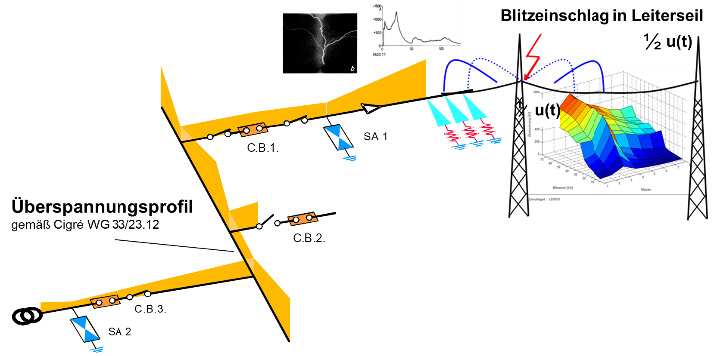
For example, Fig. 4 qualitatively shows reduction in overvoltage as a result of a lightning strike on a conductor by positioning surge arresters (SA1 & SA2) at different points in a GIS. When gas-insulated switching devices are involved, overvoltages that rise very quickly must be taken into account. When operating disonnectors, overvoltages are usually no greater than 2.0 p.u. (1 p.u. = √2 × Us / √3), although overvoltages of 2.5 p.u sometimes occur and, in rare cases, even 3.0 p.u. As a result, levels of the rapidly rising overvoltages are significantly lower than the lightning impulse voltage level and are therefore less critical. The very rapidly increasing overvoltages in the UHV range in the area of the disconnector itself play a more significant role.
When determining coordination withstand voltage, influencing factors that reduce insulation strength during the service life of a system must be taken into account. As discussed, this is done with a safety factor that takes into account effects of ageing, possible variances in manufacturing, inaccuracies in withstand voltages and other unknowns. A safety factor of 1.15 is used for the internal insulation. Environmental influences may also have to be taken into account and a safety factor starting from 1.05 applies to the outer insulation. After determining required withstand voltages, the operator can specify required insulation level. In general, reference is made to rated insulation levels based on relevant regulations, which contain different withstand voltages and test levels for each voltage.
Application Examples
1. Cost Reduction for Rail Electrification
Most railway lines in industrial Europe were built at the beginning of the 20th century and diesel locomotives are still used in some countries. While many routes in Germany, for example, have now been electrified, bridges and underpasses pose a recurring problem since they are often too low to maintain so-called ‘minimum electrical distances’, i.e. distance between electrical lines and structure. If too low, lightning strikes might cause a flashover resulting in damage to the system and infrastructure.
For example, when the Danish State Railways decided to electrify their entire network in 2015, the tender required a supplier that could also bring an innovative solution for the catenary given the numerous low bridges along rail lines. Raising a bridge and roads would be costly and in many cases not even possible due to opposition by city planning authorities. In order to meet the stringent requirements of this project, medium-voltage arresters were developed using large metal oxide resistors from the high voltage range. This enabled insulation coordination and reduced distances to be implemented.
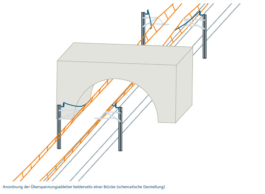
This approach of shorter distances while maintaining appropriate protection has now been adopted in the corresponding railway standard (EN 50124) revised in April 2020. This reduces lightning overvoltages to a level no longer dangerous for existing bridges and tunnels. For example, the normal distance of 27 cm for 25 kV system voltage on the overhead line could be reduced to only 15 cm with the help of an arrester. For many bridges along the Danish route this was the greatest possible distance from structures. With application of the new MO arrester, tracks no longer needed to be lowered nor bridges or overpasses raised. Arresters in this application are mounted on each side of the structure and connected to the catenary via the carrying cable (see Fig. 5). The financial outlay was relatively low considering the savings.
2. Concept of Sacrificial Arresters at 16.7 Hz Rail Electrification Overhead Lines
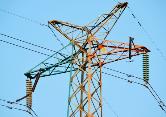
For reasons of cost and space, 110 kV railway power lines and 380 kV overhead lines are often installed on common masts. In the event of any short circuit between these systems, the railway power supply system can incur serious damage since the 380 kV overhead line network protection only recognizes the fault once serious damage has already occurred to the 16.7 Hz/110 kV traction network. One way to prevent this risk is by using so-called sacrificial arresters on the traction network. In the event of a fault, these fail quickly and are deliberately sacrificed to protect other equipment or the entire network. Loss of an arrester in this type of situation is acceptable. The arrester housing in this application is dimensioned such that it can carry the short circuit current for the required protection response time of approximately 2 seconds (see Fig. 6).
3. High Cooling Arrester (HCA) for HVDC Converter Stations
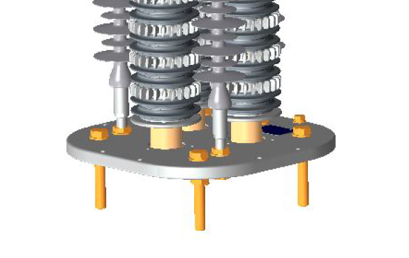
High cooling arresters (HCA) have been specifically developed to protect thyristor valves at HVDC converter stations and are characterized by an approximately 10% lower protection level and improved heat dissipation behavior than conventional arresters with housings. Here, the metal-oxide varistors (MOV) of the HCA are operated for the applied equivalent continuous voltage in the upper leakage current range of the current-voltage characteristic, which leads to increased power consumption. Since good heat dissipation to the environment is required to ensure thermal stability, HCAs have no housing and are equipped with additional cooling elements. To protect the MOVs, these are fitted with silicone screen covers with the HCA being an indoor only unit. Fig. 7 shows the lower portion of an HCA arrester with cooling elements and shielded MOVs.
Under certain circumstances, the approximately 10% lower protection level of the HCA compared to a normally housed arrester can enable the number of series-connected thyristors to be reduced by the same order of magnitude and thereby contribute to significant cost savings.
4. Line Compaction
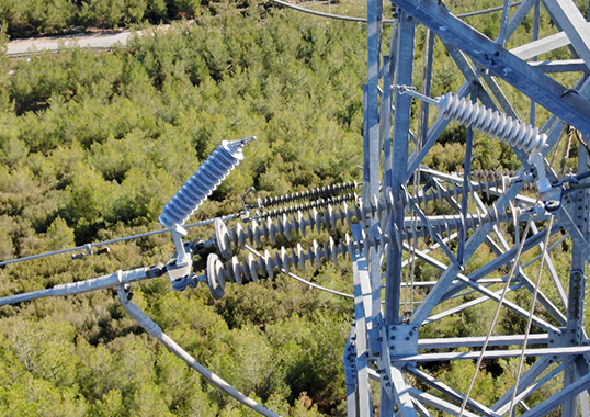
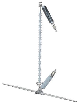
Application of line surge arresters (LSAs) has been a proven solution worldwide, especially in regions with high atmospheric lightning activity. LSAs are used to avoid brief interruptions in overhead lines due to rapidly increasing overvoltages. The two variants are the so-called NGLAs (non-gapped line arresters) without a spark gap and EGLAs (externally gapped line arresters) with an external serial spark gap. The EGLA has the advantage of lighter construction but the spark gap must be dimensioned such that it responds reliably to rapidly increasing overvoltages so as to prevent the insulator from flashing over. Fig. 8 shows an example of a 245 kV EGLA installation.
Although the effectiveness of line arresters has been proven in practical applications, they are still rarely taken into account when designing new overhead lines.
Another option when using line arresters is reducing insulation distances. With their application, distance requirements and thus structure height and width can be significantly reduced, making them far more compact. This immediately reduces environmental impact of a new overhead line projects. Moreover, for existing systems, it becomes possible to also increase the voltage to the next level along the route without having to significantly change either spans or structures. In addition, increasing transmission capacity by increasing amperage can cause related expansion of the conductor, which could fall below required ground clearance. A shortened EGLA chain, including insulators on the overhead line, can counteract such expansion so as to maintain the minimum distances required.

5. Protection at High Altitudes
In the case of switchgear located at high altitudes, atmospheric conditions can lead to correction factors that require a significantly higher insulation level of the high voltage component than would otherwise be normal for that voltage. This can require application of components for the next higher voltage level along with associated higher costs. Targeted use of arresters in these situations can help reduce costs by up to 40%. Arresters in such applications are attached directly to the device being protected. With use of an arrester, any overvoltages that might occur on the device can be kept low enough that standard insulation remains sufficient. This type of application requires detailed calculation of the coordination withstand voltage in accordance with information contained in IEC 60071-2.
6. Switchgear & GIS Interfaces
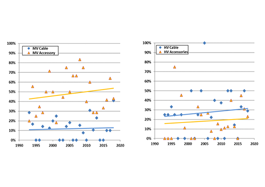
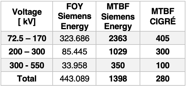
Global experience with gas-insulated high-voltage switchgear (GIS) shows high operational reliability with low error rate. In fact, numerous systems have reached a service life of more than 50 years without any increase in error rate (see Table 1).
Together with the high reliability of MO arresters, this experience can be used to carry out further system optimization. Lightning overvoltages can only be effective in direct connections to overhead lines and at substations with connected overhead lines. Gas-insulated systems have lower wave resistance than overhead lines and an incoming voltage wave is therefore significantly reduced.
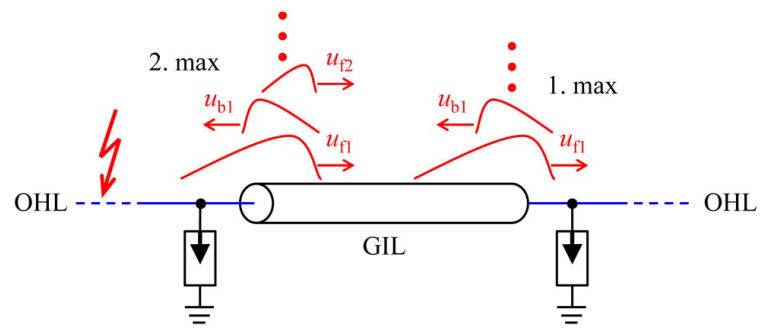
Wave impedance depends on GIS dimensions. The reduced voltage wave travels through the system and is reflected and broken by changes in the characteristic impedance. The reflected wave returns and is reflected and refracted again (see Fig 9). The superimposition of forward and reverse waves builds up different voltage maxima along parts of the system up to a theoretical maximum corresponding to twice the voltage wave arriving from the overhead line. Therefore, effects of traveling waves, including the MO arrester, must be taken into account during system design.
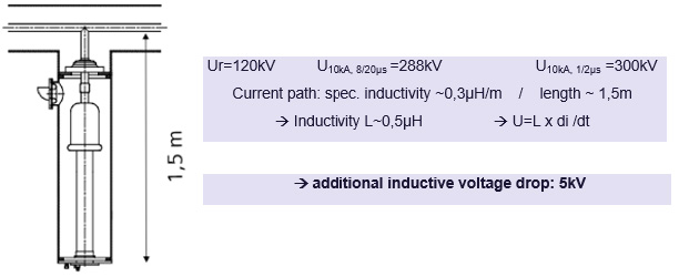
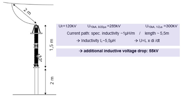
Voltage stress can be reduced by placement of MO arresters. Integrated GIS arresters are especially advantageous in terms of voltage reduction because of lower inductance compared to outdoor arresters. The result is up to 15% lower residual voltages by comparison with outdoor arresters (see Figs. 10 and 11).
Reactive power compensation reactors that may be provided also have a voltage limiting effect, which must be taken into account in overall system optimization. Overall standard lightning impulse withstand voltage (LIWV) of equipment can be reduced using arresters. Table 2 shows the effects, according to IEC 60071-1, for LIWV levels of 1050 kV and 1425 kV using the example of a 420 kV GIS outlet with CO2-neutral compressed air (i.e. clean air versus SF6 insulation). There is no doubt that dimension, weight and cost can be significantly reduced with the same reliability with the lower LIWV levels. These advantages increase when compressed air is used as insulating gas instead of SF6.
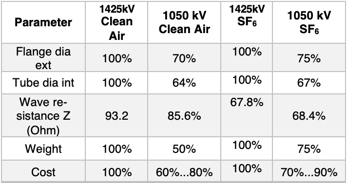
Table 2: Influence of BIL Protection Level in Design of 420 kV GIS Bushing on Dimension, Weight & Cost
Conclusions
High quality metal oxide arresters are essential for the safe operation of today’s AC and DC energy systems. Making smart choices and taking insulation coordination into account allows protection level to be optimized for many electrical system applications, thereby significantly reducing costs.
Reference Literature
[1] H. Ito, N. Uzelac, F. Richter, R. l. Roux, W. Pepper, L. Peng, A. Manim, I. Hategan, „ CIGRE Reliability Survey on Equipment”, A3-201, e-Paris 2020
[2] Volker Hinrichsen: “Metalloxid-Ableiter in Hoch-spannungsnetzen”; www.siemens-energy.com/arrester; 3. Auflage / 2012
[3] IEC 60099-4, Ed. 3.0: Surge arresters – Part 4: Metal-oxide surge arresters without gaps for a.c. systems
[4] IEC 60071-1: Insulation Co-ordination, Part 1: Defi-nition, principals and rules
[5] IEC 60071-2: Insulation Co-ordination, Part 2: Appli-cation Guide
[6] IEC TR 60071-4, Insulation co-ordination – Part 4: Computational guide to insulation co-ordination and modelling of electrical networks
[7] CIGRE WG 15.03: GIS insulation properties in case of VFT and DC stress. CIGRE 15-201, 1996
[8] CIGRE JWG 33/23.12: Insulation co-ordination of GIS: Return of experience, on site tests and diagnostic techniques. ELECTRA No. 176, Feb. 1998, S. 67 – 97
[9] CIGRE WG D1.03, Very Fast Transient Overvoltages (VFTO) in Gas-Insulated UHV Substations, CIGRE technical brochure No.519, 2012
[10] M. Kuschel: Isolationsbemessung von GIS, FGH Se-minar Isolationskoordination, 19. – 20. Februar 2019
[11] IEC 62271-1, High-voltage switchgear and control-gear – Part 1: Common specifications for alternating current switchgear and controlgear
[12] G. Bromley, “Introducing Surge Arrester Technol-ogy” in Rail Engineer, Issue 158, 2017
[13] M. Westenthanner, „Opferableiterkonzept für die Pa-rallelführung von 110-kV-Bahnstromleitungen und 380-kV-Freileitungen“in eb-elektrische Bahnen 2016
[14] R. Göhler, V. Brendler, V. Hinrichsen, J. Shaikh, M. Weyer, M. Giessel, CIGRE A3-112 Arresters with ad-vanced cooling performance for protection of valves in HVDC converters, 2016
[15] B. Robben, M. Jolic, „Reducing Clearances by Inte-gration of Externally Gapped Line Arresters on HV Transmission Lines” in INMR 2019
[16] Siemens Energy Betriebsanleitung, Bestell_Nr. 92800096100a
[17] CIGRE 3rd Survey „Final Report of the 2004 – 2007 International Enquiry on Reliability of High Voltage Equipment, Part 5 – Gas Insulated Switchgear (GIS)” WG A3.06, 10/2012
[18] Felix Goll, Rolf Witzmann: “Lightning Protection of 500-kV DC Gas-Insulated Lines (GIL) With Integrated Surge
[19] O. Völcker, H. Koch, “Insulation co-ordination for gas-insulated transmission lines (GIL),” in Proc. IEEE Power Eng. Soc. Winter Meeting, 2000, vol. 1, pp. 703–711
[20] Cigre JWG 23/21/33-15: “Gas Insulated Transmis-sion Lines (GIL)”, Technical Brochure 218, 2003
[21] E. Kynast, Isolationskoordination und Hochspan-nungstechnik in den UHV-Technologien, Dissertation, TU Graz, 2011 [22] M. Kuschel et al, Entwicklungsstand, Vor-Ort-Erfah-rungen und Ausblick zu SF6-freien Hochspannungs-schaltanlagen, VDE Hochspannungstechnik, 11 / 2020