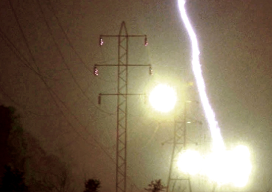
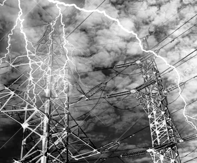
In many countries, lightning accounts for a large share of line tripping and is linked to both season and specific region. Based on the physical processes involved, lightning induced overvoltages fall into one of two broad categories: those caused by direct strike to towers, shield wire or conductor; and those where lightning strikes the ground near lines, generating an induced overvoltage on conductors. Experience demonstrates that the former imposes a far greater hazard and that the latter most threatens lines of 35 kV or below.
Based on where a line is hit, overvoltages from direct lightning strike are also of two types. In the first case, lightning strikes a point on the tower or shield wire and the resulting current causes its potential to ground to rise significantly. When this difference in potential between lightning strike point and conductor exceeds the lightning impulse discharge voltage of the line’s insulation, flashover or breakdown of the air gap occurs. By contrast, should the absolute value of the tower or shield wire potential at the moment of lightning strike be higher than that of the conductor, there is back flashover. In the second case, overvoltages generated by lightning bypassing the shield wire and striking the conductor are shielding failures.
The performance of a system’s lightning protection can be measured using two indices – lightning withstand level and lightning related tripping rate. The former refers to the maximum amplitude of lightning current (in kA) that the line can withstand without leading to insulation flashover under direct lightning strike. The higher this is, the better will be a line’s lightning performance. Lightning related tripping rate refers to the number of trips on a line (per 100km/year) under standard conditions or after being converted to the equivalent of 40 lightning days per year. Lightning tripping rate is therefore a comprehensive index of a line’s lightning protection performance.
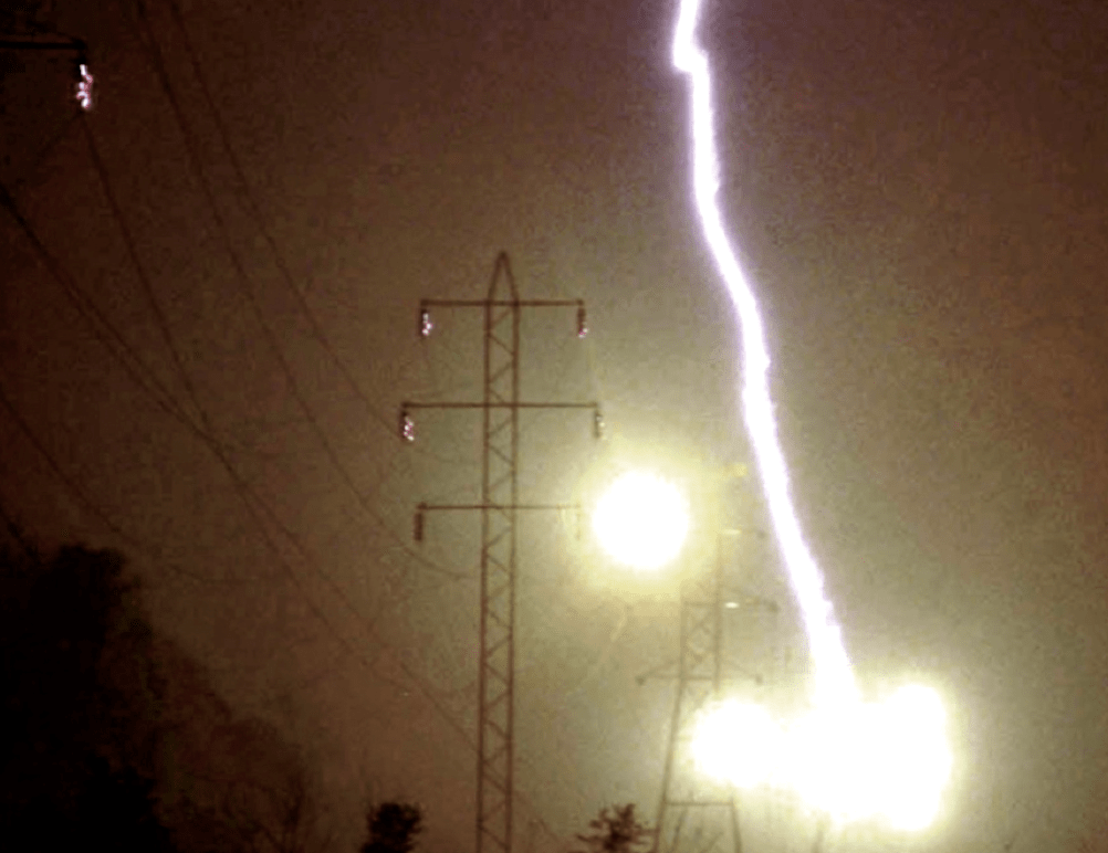
Since shield wire is often installed along the length of a line of 110 kV and higher, it has been widely assumed that lightning related tripping on such lines was due mainly to backflashover while incidence of shielding failure was lower. But statistics from some countries demonstrate the opposite. For example, past lightning related tripping rates on Chinese power lines have shown that most were due to shielding failure and much less to backflashover or other causes. Moreover, tripping of 750 kV and ±500 kV lines were virtually all due to shielding failure. Indeed, comparative rates of shielding failure as a proportion of all lightning tripping on 66 kV, 110 kV, 229 kV, 330 kV and 500 kV lines were such that the higher the voltage, the higher the percentage of shielding failure related tripping.
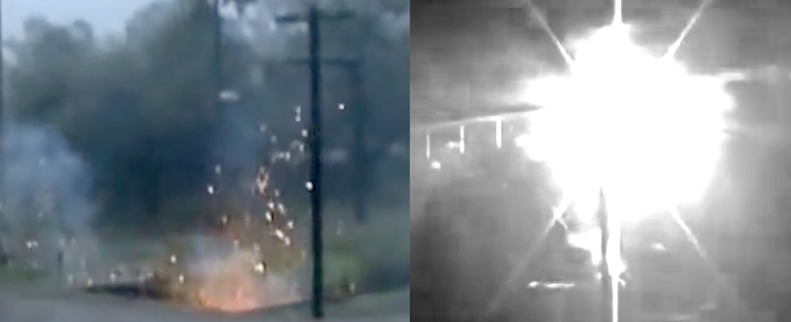
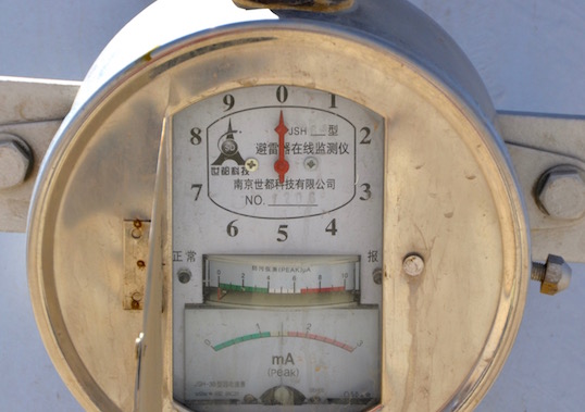
Measures to increase the lightning withstand level of a transmission line and reduce lightning related hazards include: decreasing grounding resistance of towers; adjusting protection angle of the shield wire; using a lightning protection differentiation design for double circuit towers; installing additional lightning rods or line surge arresters (TLSAs) in areas with highest risk. Moreover, using lightning monitoring equipment helps in locating and replacing damaged insulators in a timely manner.
Dealing with backflashover has a distinctly different focus than for shielding failures. Decreasing ground resistance of towers is highly effective in preventing backflash related tripping; the main measures to prevent shielding failure are decreasing a wire’s protection angle or installing more lightning rods and line arresters.
The lightning withstand levels of transmission lines in the event of shielding failure are low. Calculated lightning shielding failure withstand levels for 110 kV, 220 kV, 330 kV and 500 kV transmission lines are only 7 kA, 12 kA, 16 kA and 27 kA respectively. In places such as China, for example, the probability of lightning current over 20 kA is 59% and that over 50 kA is 27%. As such, occurrences of shielding failure will typically lead to line tripping and therefore demand more attention to prevent them, especially on higher voltage lines.
Line arresters can significantly reduce lightning related tripping and their practical application has proven remarkably effective. If their cost can be further reduced, they would probably be used far more widely. At the same time, UHV AC lines have an additional shield wire installed above the center phase conductor on critical sections to increase withstand performance and reduce lightning shielding failures.
It is also important to increase the lightning withstand level of insulators. Since composite insulators offer superior withstand to pollution flashover, their insulation distances are usually shorter than for equivalent porcelain or glass strings. Moreover, a composite insulator’s grading ring’s lightning withstand level may be relatively low. Given that the lightning withstand level of 110 kV lines is already low, the net negative impact on lightning performance when composite insulators are specified can be significant. Power companies have already noticed this and their specification of composite insulator lengths is no longer based solely on pollution flashover performance but also takes into account effect on lightning withstand level. Still, as long as the air gap between the grading rings of composite insulators is not less than that on porcelain or glass strings, a line’s lightning withstand level will not decrease.
Finally, any discussion of lightning related hazards to lines must consider not only lightning related tripping rate but also failure rate due to lightning. If reclosing is successful on a line struck by lightning, no service interruption will result. Given this, installing parallel-connected protection gaps on insulator strings helps keep the arc from a lightning flashover sufficiently far from the surface to avoid interruption due to damaged insulators.
Prof. Guan Zhicheng
(retired) Tsinghua University, Shenzhen Campus
[inline_ad_block]

