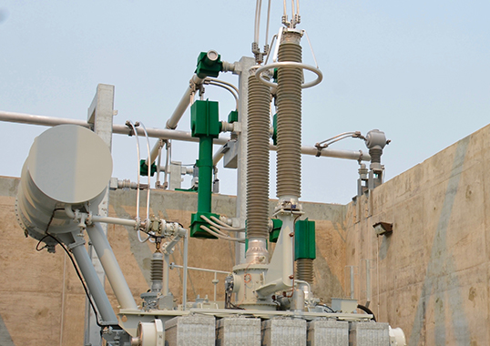
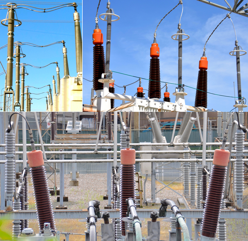
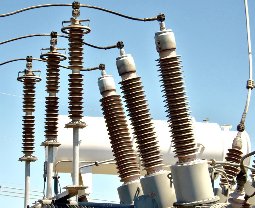
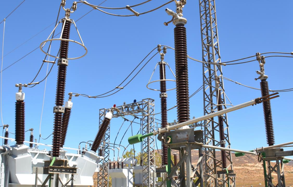
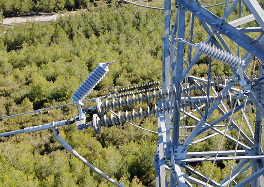
This edited past contribution to INMR by Jonathan Woodworth deals with the issue of how far an arrester can be located from a transformer while still ensuring an adequate margin of protection. Locating the arrester as close to the transformer bushing as possible is what is usually recommended but not always feasible, especially at higher system voltages.
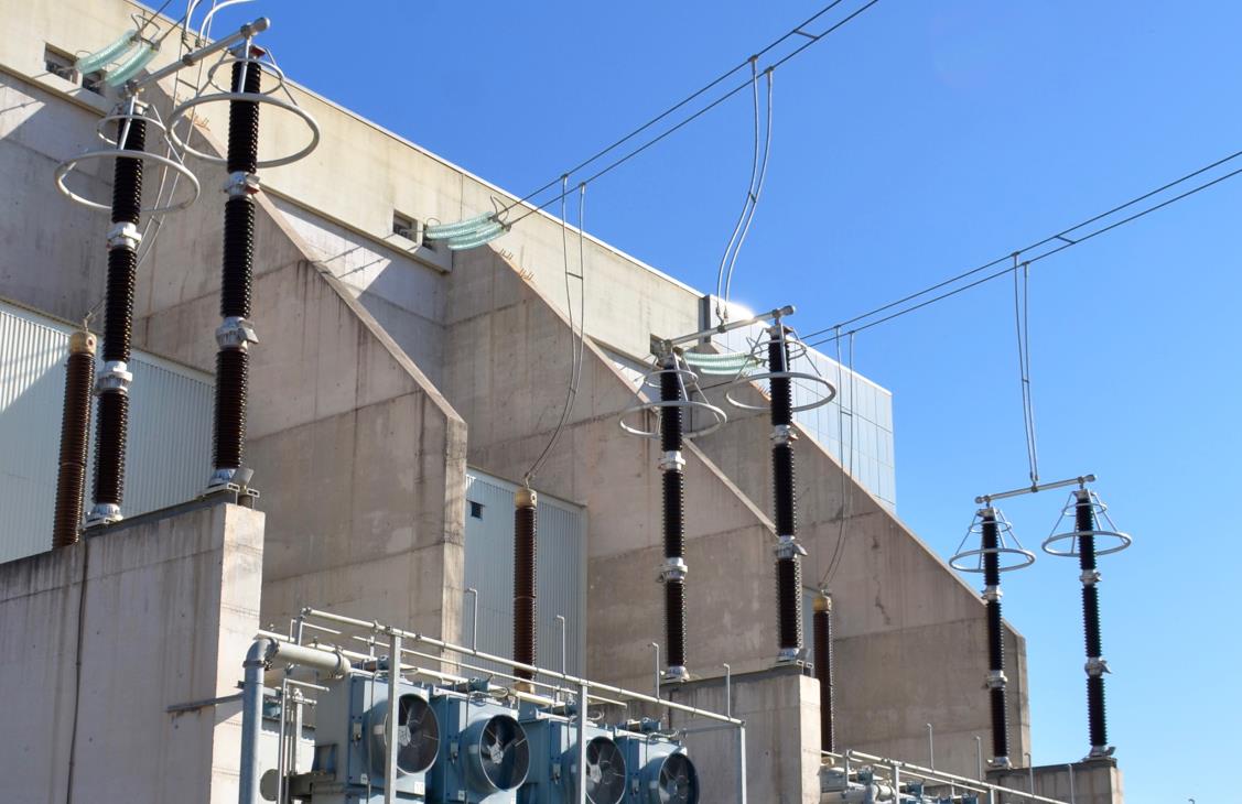
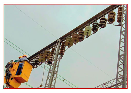
At voltages of 400 kV and higher, arresters can become too large to be easily supported by the transformer’s body and must be mounted on separate structures and pedestals. Such ‘extended’ separation distance is also needed in cases where transformers have to be easily moved for repair. For example, access roads for this purpose can sometimes result in up to 30 m of separation of arrester from transformer.
Unfortunately, separation distance (or protective zone) of this magnitude can result in reduced protection when a fast rising surge enters the station from an overhead line at nearly the speed of light. When the surge hits the arrester, voltage is indeed reduced – but not to zero and, at best, to the discharge voltage of the arrester. The resulting surge traveling past the arrester is reflected at the transformer, which can result in voltage doubling if the separation distance is sufficiently great. While in most cases reflected voltage only increases incoming surge by a few percent, it is this traveling wave phenomenon and the associated reflection factor that highlight the importance of separation distance.
Help has been offered in IEEE’s Application Guide on Arresters C62.22 and also in IEC 60099-5. In C62.22, a formula determines the maximum distance at which an arrester can be mounted yet still achieve a protection margin of 15%. To illustrate how this formula works in graphical terms using a transient program (ATP), below are simulation results for a substation with arresters located 1 m (Fig. 2), 15 m (Fig. 3) and 30 m (Fig. 4) from 500 kV transformer bushings. All other parameters remain the same and these numbers were chosen only to demonstrate simple insulation coordination in a substation. The arresters are mounted on a pedestal that results in 5 m from earth ground to the base with their tops located 1m from the incoming line.
As shown in Fig. 2, the voltages at the arrester and transformer are, as expected, identical and peak at 1326 kV. This leaves a margin of protection of 16% for a 1550 kV BIL transformer, which is the minimum recommended according to IEC and IEEE. The simulation in Fig. 3, with 15m distance between arrester and transformer bushing, sees margin of protection reduced to only 8%, which is less than recommended but still not above the transformer’s BIL of 1550 kV.
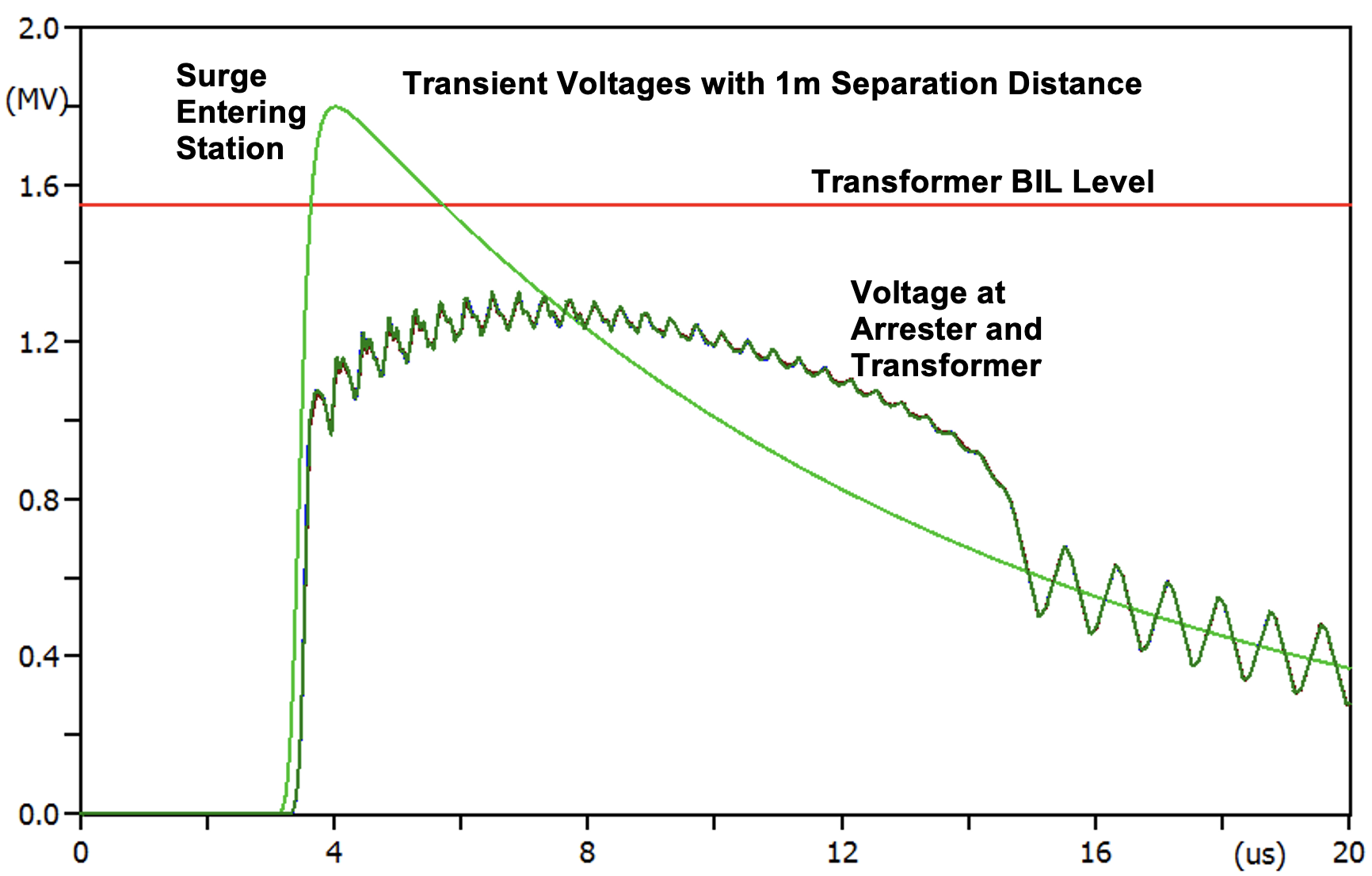
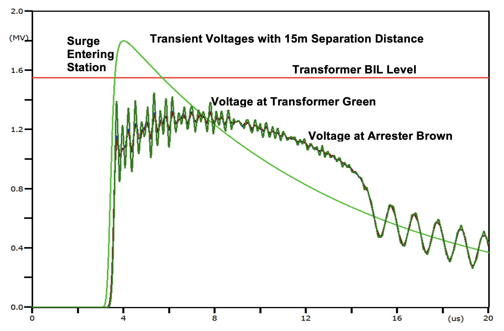
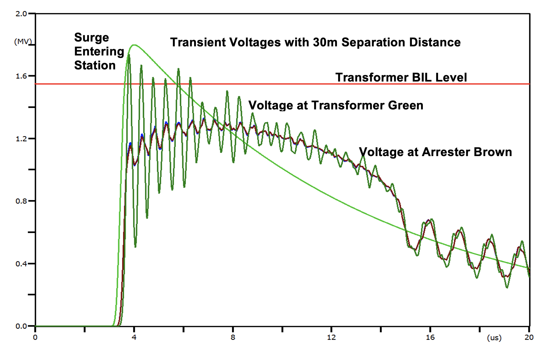
Fig. 4 makes it clear that 30 m separation distance would result in the voltage at the transformer exceeding its withstand level (BIL), meaning that a fast rising surge entering the station in such a case could cause serious damage. Therefore, if for whatever reason it became necessary for the arrester to be located 30 m from the bushing, a transformer with higher withstand (BIL) would have to be specified.
Separation distance is also a consideration with other equipment in the substation. For example, if CCVTs, CVTs, PTs or breakers are sited at an end point on a short line, they would experience the same excessive transient voltage as in the transformer examples above. An arrester should therefore ideally also be installed to protect them. Indeed, protecting high value assets against transients is an important part of substation design and placing arresters at the proper distance from the equipment they serve is critical to ensuring adequate protection in every case.
[inline_ad_block]

