This edited contribution to INMR by Jonathan Woodworth, Convenor of IEEE WG SPD 3.3.11 (Continuous Revision of C62.11) and Co-Convenor of IEC TC37 MT4 (Continuous Revision of 60099-4), reports on recent progress towards better harmonizing IEEE and IEC arrester standards.
Listen to Online Lecture on Harmonizing IEC and IEEE Arrester Standards by Jonathan Woodworth
Background
The goal of an IEEE Working Group (WG) meeting in May 2013 was to revise C62.11 and continue evolution of this standard toward rationale-based tests that better align with IEC standard 60099-4. Although it was hoped to have this completed by the end of 2018, it soon became clear that complete harmonization of these standards was not going to be possible. Unfortunately, the formal methods available to using the IEEE/IEC Dual Logo standards development process for two existing standards did not offer a reasonable path toward harmonization. It was therefore decided to move ahead with informal harmonization by developing similar, though not identical, test methods that could be adopted by both standards bodies as part of their normal cycles and organizations. To that end, there will soon be an IEEE standard whereby most major laboratory tests will be useable to produce both IEC and IEEE certified test reports.
A second goal when this process began was to create a set of tests that applied to transmission line arresters. For example, mechanical tests applicable to this type of arrester are not covered in C62.11 and only partially in 60099-4 and -8. While a WG task force was created initially to address this issue, it was soon realized that the IEEE/IEC Dual Logo process could apply and that process was initiated. At present, there is a joint IEC/IEEE WG on a new line surge arrester standard that covers both non-gapped (NGLAs) and externally gapped line arresters (EGLAs).
It should be noted that harmonization of IEEE C62.11 and IEC 60099-4 actually started several years ago when the current version of short-circuit tests was written. In that case, the section was written by a joint IEC/IEEE group and it was agreed at the time that these sections would be adopted in both standards. There are some minor differences in this section but if a short circuit test is completed for IEEE certification, with minor modification it can also be applied toward IEC certification.

CLICK TO ENLARGE
Further to harmonization efforts, Edition 3.0 of 60099-4 (2014) adopted the terms ‘Distribution’ and ‘Station Arresters’. This edition also abandoned the notion of classifications based on line discharge class and moved instead toward current charge/energy classifications that focus on an arrester’s energy and charge withstand capabilities. C62.11-2019 has adopted the same approach to arrester classification.
General Considerations
Three fundamental differences between IEEE C62.11 and IEC 60099-4 are:
1. 11 covers gapped metal oxide surge arresters (MOSAs) as well as non-gapped MOSAs while 60099-4 does not;
2. the IEEE standard covers arresters only up to 460 kV MCOV. Above that, tests need to be agreed upon between customer and manufacturer. IEC 60099-4 covers all arrester ratings above 1000V AC;
3. 11 has obsoleted the term ‘Rated Voltage’ of an arrester and now refers to MCOV in regard to its AC rating. This ends the nearly 40-year practice of giving MOSAs two AC ratings, which only confused users while serving no practical purpose. It is possible that 60099-4 will follow suit and change Ur (rated voltage) to the 10 second withstand voltage in its next edition, as now being discussed.
Arrester Classifications
Distribution Arresters
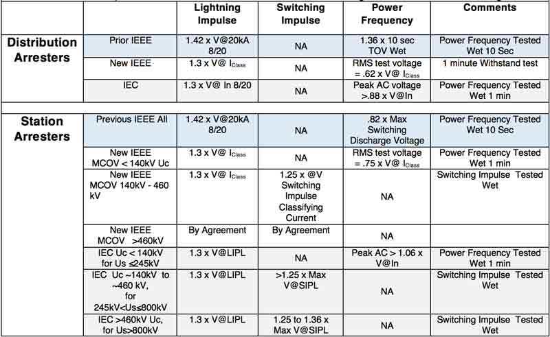
IEC and IEEE distribution arrester classifications are the same except for classification name. This is the first time that distribution arresters have a charge transfer rating as well as a thermal energy rating. See Table 1 for details.
Station Class Arresters
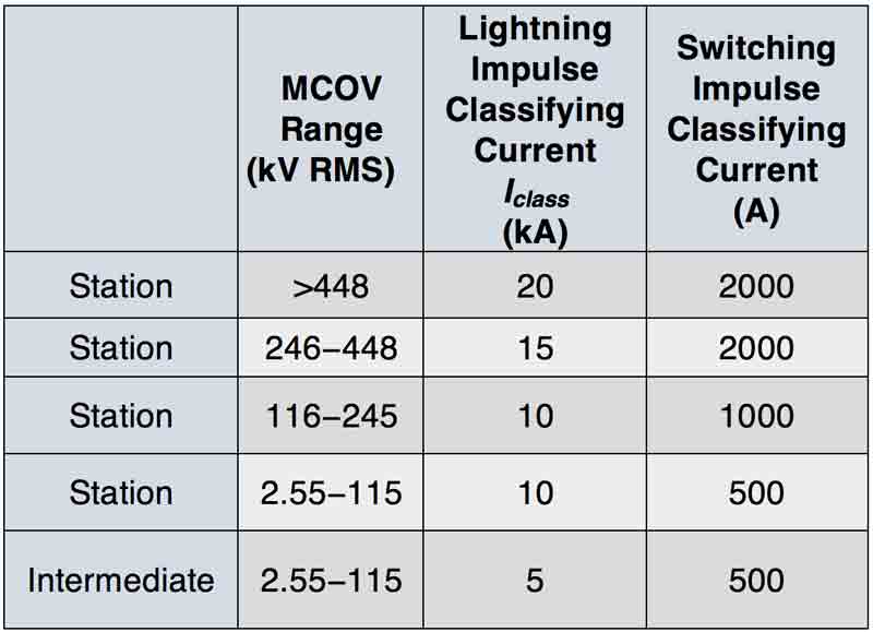
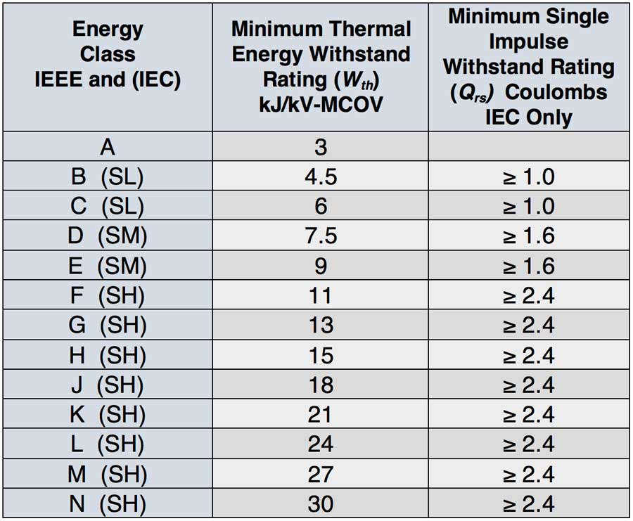
Station class arresters require two tables to define their classification. Table 2 shows impulse characteristics while Table 3 defines energy withstand ratings of the arrester. IEC ratings are different (also shown in Table 3) but tests to verify these ratings are nearly identical.
CLICK TO ENLARGE
CLICK TO ENLARGE
Arrester Housing Insulation Withstand Tests
Station Class Arresters
Tests to quantify housing withstand level for impulse and power frequency voltages can be traced back to the earliest standards of the last century. Both IEC and IEEE standards have sections for station and distribution class arresters. The objective in both standards is to demonstrate that the housing of the arrester will always withstand more voltage than it will ever experience in service. Because arrester housings are protected by the clamping voltage action of the internal metal oxide disks, an arrester is said to be ‘self-protected’. Because of this unique characteristic of the housing, a special note was included in test rationale of C62.11-2019 that states:
It should be noted that the impulse withstand levels of arrester housings are not to be compared to BIL or CFO levels of insulators. Due to the arrester’s self-protecting nature, the arrester housing can have a lower withstand voltage than the rest of the system without any negative impact on the system withstand level.
Also, for this reason, arresters used in standard applications do not generally have a standardized insulation withstand rating.
Changes in housing insulation withstand tests in C62.11-2019 are summarized below:
1. For all arrester ratings, standard design elevation was changed from 1800 meters to 1000 meters, better aligning with other IEEE standards as well as with IEC 60099-4.
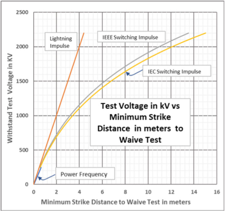
2. Added is the option of waiving testing if sufficient strike distance of the arrester design is used. Formulae are provided for lightning impulse and switching impulse. In addition, AC withstand voltages are given that instruct test personnel on how to determine withstand voltage of the sample based on its physical dimensions. If calculated withstand voltage exceeds specified test voltage, testing can be waived and this is the first time in C62.11 where a test can be waived if the arrester is shown to be designed significantly above standard. Also, C62.11 adopted a slightly less conservative formula than IEC 60099-4 for the switching surge calculation (see Fig. 1).
CLICK TO ENLARGE
3. IEEE adopted the IEC method of testing arrester housings with MCOV ratings above 140 kV. This new test method uses switching impulse voltage instead of AC voltage to verify the arrester’s low frequency wet withstand level. Such higher rated arresters are now tested with a lightning and a switching surge impulse to certify housing withstand and not with AC.
4. For arresters with MCOV rating less than 140 kV, switching surge withstand tests are not used and the familiar AC withstand test is applied instead. For harmonization, the IEEE standard had to accept a 1 min wet withstand test instead of the 10 second wet withstand test of the past. Since arresters are overdesigned in this area, this was not a difficult change (see Fig. 1 for details).
Listen to Other Online Lectures on Arresters
5. Specified test voltages are similar between the two standards but there have been some compromises. For example, sometimes a less conservative value is accepted by IEEE while other times values are more conservative. In all cases, test voltage requirements are lower than actual design levels presently in use. Also, test voltages specified always have a built in safety margin for 1000 meter altitude (i.e. 13%) as well as variations in impulse current of 10 to 15%.6. Because C62.11 provides tests for both gapped and non-gapped MOSAs, the test voltages in this section are derived from either the discharge voltages or 1.2/50 µs sparkover voltage. In 60099-4, there is no accommodation for such.
Distribution Class Arresters
Open Air Polymer-Housed Arresters
For distribution class arresters, housing withstand is tested, as in the past, with lightning impulse discharge and power frequency withstand tests.
Even though test methods are similar, to harmonize the standards details were modified, as follows:
1. The power frequency withstand test became a 1 minute instead of a 10 second test. This lowered test voltage slightly;
2. The lightning impulse withstand test remained the same, with slight reduction in level due to change in altitude from 1800 m down to 1000 m;
3. For the first time in IEEE arrester standards, if strike distance of the arrester is long enough, testing can be waived. The same calculations used to predict station class withstand voltage based on length are used for distribution arresters. If calculated voltage exceeds the specified minimum withstand voltage, testing can be waived.
In C62.11, the withstand voltage of the insulating hanger is evaluated for its power frequency withstand level. It must withstand a 1.5pu MCOV voltage for 10 seconds wet, between hanger mounting point and the ground end of the arrester. IEC 60099-4 has no equivalent test requirement.
Deadfront Arresters
One area not harmonized with IEC for distribution arresters is deadfront arrester design. Test requirements were significantly changed in C62.11 based on changes in IEEE 386. Test requirements in 60099-4 will need to be updated to meet these new requirements since this is basically an IEEE only design.
CLICK TO ENLARGE
Discharge-Voltage Characteristics Test
This test was harmonized with IEC in the 2012 edition of C62.11 and is the same as IEC 60099-4, with one exception: in the IEEE standard, maximum current level to test is 40 kA but in IEC it is 20 kA.
Power-Frequency Sparkover Test
This test applies only to gapped metal oxide surge arresters and is harmonized with IEC 60099-6.
Impulse Protective Level Voltage-Time Characteristic Test
This test applies only to gapped MOSAs and is harmonized with IEC 60099-6.
Accelerated Ageing Test of Metal Oxide Discs
The procedures for this test are nearly identical between C62.11 and 60099-4 however pass/fail criteria are not the same. In both cases, this test must be satisfied for discs of the same design to be used in the rest of the certification process. If this test is not passed, there is no recourse but to use discs of different design. This test has not been changed in C62.11-2019.
Accelerated Ageing Test of Polymer-Housed Distribution Arresters with Exposure to Light & Electrical Stress
This section is unique to C62.11 and has no equivalent in 60099-4. This test partially overlaps with salt fog testing but the salt fog test does not evaluate insulating hanger. For this reason, this test needs to be in the next edition of C62.11 and work will be required to harmonize both standards.
Accelerated Ageing Test of Polymer-Housed Arresters with Exposure to Salt Fog
This test is harmonized with IEC 60099-4 Section 10.8.17.2. There is discussion in both Working Groups and this section may change in the next edition of each standard.
Contamination Test
This test is similar to Annex C.7.1 of IEC 60099-4. However, these two sections are not harmonized and much work will be needed to achieve harmonization.
Distribution Arrester Seal Integrity Design Test
There is no equivalent test in 60099-4 or 60099-6 and IEC may need to adopt this test in its entirety.
Radio-Influence Voltage (RIV) Test
This test applies to arresters with an MCOV > 70 kV. Procedure and results are harmonized with IEC.
Switching Impulse Energy Rating Test (Wth)
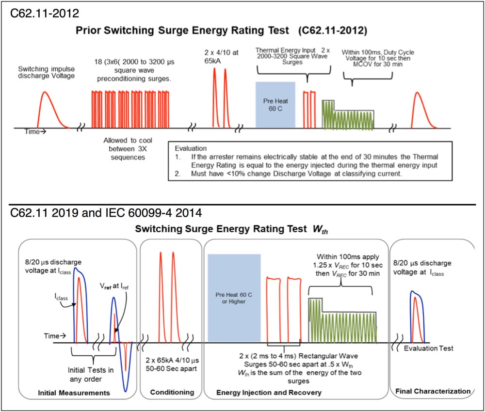
This test, first introduced into the IEEE with C62.11-2012, is similar to the previously titled: Operating Duty Cycle Test for Station Class Arresters. This test is fully harmonized with 60099-4. The primary difference between C62.11-2012 and the next edition is elimination of the 18 pre-conditioning impulses. It has been agreed based on research that the only effective pre-conditioning of metal-oxide discs comes from high current impulses and not from lower current surges.
The test is now referred to as the Wth rating test. Resulting energy ratings are the same in the new edition as in the 2012 edition but now defined as Wth, as in 60099-4. Fig. 2 compares the procedures of past and present tests.
CLICK TO ENLARGE
Single-Impulse Charge Transfer Rating Test (Qrs)
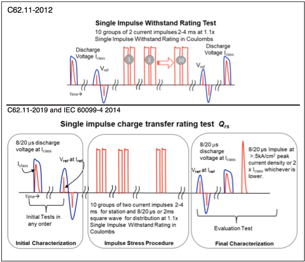
This test was previously called the Single-impulse Withstand Rating Test but, for the sake of harmonization, is now referred to as a Charge Transfer Rating Test with the parameter of importance being, Qrs. The most significant difference is not the test itself but that it is now applied to all arresters – not just to station class arresters as in the past. This change, along with final higher current impulse at the end of the test, harmonized the test with IEC 60099-4 and IEC 60099-6. Fig. 3 compares the details of past and future test procedures. The difference between IEC and IEEE with regard to Qrs rating is that, in IEEE, there is no minimum for station arresters whereas IEC gives minimum ratings. Either standard may change in the next cycle as more Qrs data evolves.
CLICK TO ENLARGE
Operating Duty Test for Distribution Arresters (Qth)
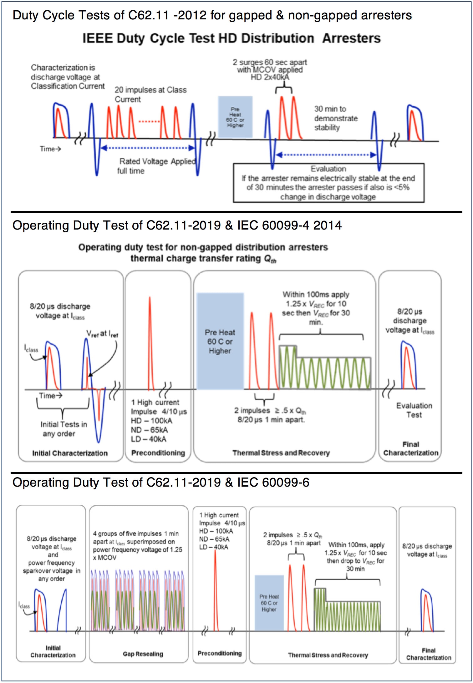
The Operating Duty Test represented a big change for IEEE to harmonize with IEC 60099-4 however, after long discussion, occurred with separation of the test into gapped and non-gapped procedures. As of its next edition, C62.11 will have an improved duty cycle test that verifies thermal charge transfer rating (Qth) of distribution arresters. Fig. 4 compares details of past and future test procedures.
CLICK TO ENLARGE
The fundamental difference is that the 20 low current (10 kA) pre-conditioning impulses are replaced by a single high current impulse. This change was accepted because activity within CIGRE WG A3.17 (published in TB 544-2013) clarified that the important condition to verify thermal stability was total charge and amplitude of the pre-conditioning impulses rather than number of impulses. Because the gapped metal-oxide arrester is not included in this test, IEEE accepted removal of pre-conditioning impulses at 10 kA with rated voltage applied.
The operating duty test for gapped metal-oxide arresters is harmonized with IEC 60099-6. It is essentially the same as for the non-gapped metal oxide arrester test except it still has 20 pre-conditioning impulses with AC voltage applied in order to verify durability and long-term dependability of the gaps.
Temporary Overvoltage (TOV) Test
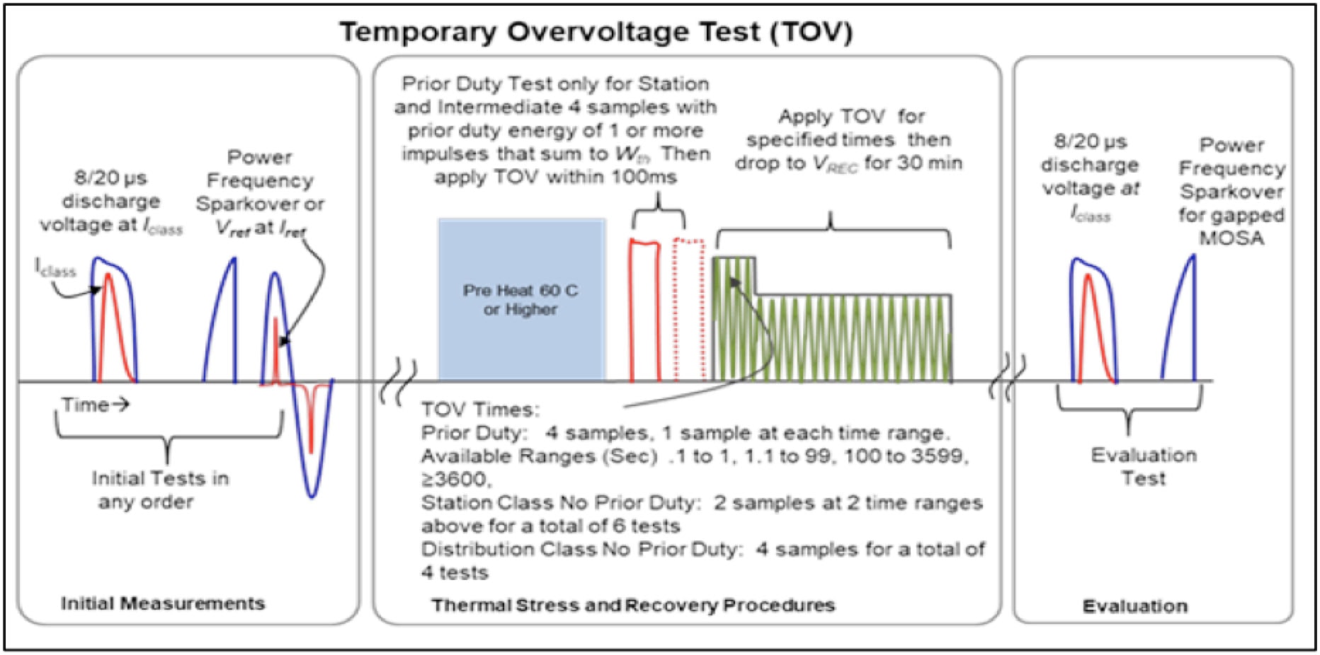
The TOV test was the last major test to be harmonized to IEC 60099-4. Since test procedures were already similar, only modification to overvoltage duration was needed. In the end, while not identical, the two tests can still be executed so that they meet both standards, if needed.
CLICK TO ENLARGE
Short-Circuit Test
This test has been harmonized now for over 10 years, with only minor differences and can be executed such that it applies to both IEC and IEEE standards.
Failure Mode Test for Liquid-Immersed Arresters
Although there are similar parts, this section of tests is not yet harmonized between IEC and IEEE. Number of samples to test and fail open designs still need to be harmonized but this could easily be achieved in the next edition of either standard.
Deadfront Arrester Failure Mode Test
Again, there are similar parts between the standards when it comes to this test but this section is not yet harmonized. One issue, for example, is that the IEC test includes Separable Arresters. This test could easily be harmonized in future editions.
Distribution Arrester Disconnector Test
Previous editions of C62.11 required running a Low-Current Long-Duration (LCLD), High-Current Short-Duration (HCSD) and Operating Duty Test on disconnector design. Since LCLD and HCSD tests were eliminated and rolled into the new Operating Duty Test and Single Impulse Withstand Test, the disconnector test had to follow suit. This test is now fully harmonized with new test requirements in C62.11 and harmonized with IEC 60099-4 and 60099-6.
Maximum Design Cantilever Load (MDCL) & Moisture Ingress Test for Polymer-Housed Arresters
The equivalent IEC test, referred to as Bending Moment (polymer-housed arresters), appears in Section 10.8.11 of 60099-4-2014. This test was harmonized in the C62.11-2012 edition but this related to a draft version of 60099-4 while changes were eventually made in the final IEC version. At the moment, if IEEE testing includes tests at 1000 cycles, results could be used for both IEC and IEEE certification. Either the next edition of 60099-4 will drop the 1000 cycle requirement or IEEE will add it.
Ultimate Mechanical Strength-Static (UMS-Static) Test for Porcelain-Housed Arresters
The bending moment test in 60099-4-2014 Section 8.11 is the equivalent test for porcelain-housed arresters. Though the objectives are similar, test definitions and procedures are different. Work will be needed to harmonize this test and this may be possible in the next editions of each standard.
Seismic Capability Verification
This test requirement can be fully harmonized assuming the IEC customer accepts the test procedure as per IEEE 693. Annex G of IEC 60099-4 lists acceptable national standards that can be used to test arresters and the IEEE 693 standard is on this list.
Summary
The majority of IEC and IEEE Arrester design tests are now harmonized. The few that remain are minor tests and will probably be harmonized in upcoming cycles.

