Electrical power systems have become increasingly complex and this has lead to greater demand for all types of laboratory testing. At the same time, there are also growing requests for ‘non-standardized’ tests on objects such as HVDC valves, AC and DC cables, line insulators, cable accessories, wall and transformer bushings, optical instrument transformers and different types of station posts.
One of the factors behind this trend is that network equipment is often exposed to service conditions not covered by design and type testing. Another factor is that requirements set out in some of today’s standards are regarded as not stringent enough to reflect what actually occurs in the field. All this has lead to testing with increased durations, new test methodologies and more demanding pass requirements.
Non-standardized tests impose special requirements not only on the skills of testing staff but also on the test equipment itself, that needs to be flexible and easily moved despite being large and heavy. This edited 2019 contribution to INMR by experts at STRI in Sweden reviewed examples of non-standardized laboratory testing.
Transient Tests
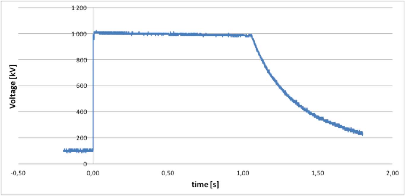
Type and development tests are carried out on a range of equipment and components exposed to different types of HV transients during service. Such tests see creation and application of different types of transient overvoltages. While these have typically been mostly for research and development purposes, there is now also a growing requirement coming either from equipment manufacturers or from grid operators. For example, testing was performed to create a voltage wave applied to the test object with rise time of less than 20 µs, duration of at least 1.05 s and amplitude of 1010 kV. Similarly, another test required having a DC voltage of 450 kV of opposite polarity on one side and applying the DC transient voltage on the other. Two DC generators, in combination with a circuit breaker, were used for this test.
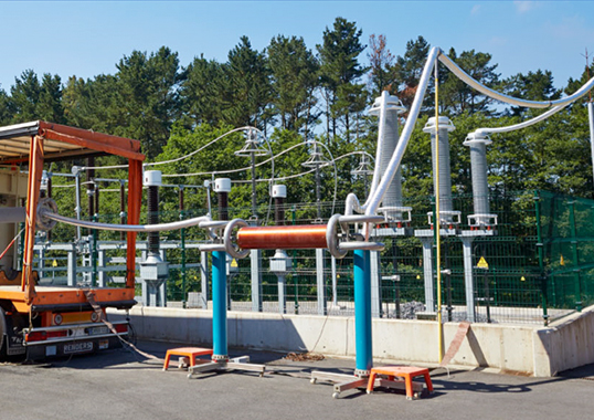
During 2018, STRI received a request to perform a test to create a transient with resonance frequency, dc voltage level and time duration as close as possible to what had been measured in the field. While test circuit parameters were provided by the customer, STRI designed the test layout which consisted of an outdoor 70 m long bus bar together with a circuit breaker that was opened and closed to create the DC transient voltage.
Ice, Snow & Low Temperature Tests
While there are basic standards governing how to carry out tests under certain environmental conditions, such as ice, customers often want to simulate specific local conditions as closely as possible. This means going outside present standards. For example, STRI has performed a number of tests under ice, snow and low temperature conditions, as discussed below:
Development of Ice Tests
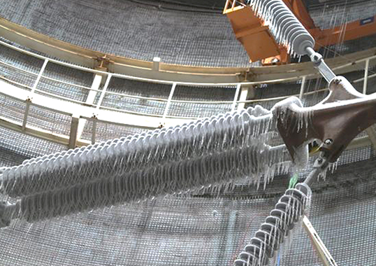
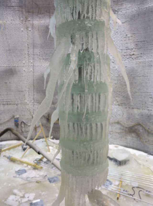
STRI has for years worked closely with customers to develop suitable test methods for ice and snow. To make such testing both representative and as cost effective as possible, the Ice Progressive Stress (IPS) test method was developed. The test consists of two phases – ice deposition under service voltage and evaluation of flashover performance by increasing test voltage to flashover. As such, results provide more information when compared to a normal withstand test. The IPS test method has been applied successfully in a number of projects and was eventually included in an IEEE Guide for ice test methods and procedures. Fig. 2 shows an example of ice deposited under voltage. In this specific case, a DC-voltage was applied to the insulator chain during ice build up. The conclusion was that this is the preferred test method since it applicable for full-scale testing, repeatable as well as cost and time effective.
Development of Snow Test
Testing under snow conditions is difficult since it involves potentially large variations in key parameters that need to be controlled, such as type of snow, conductivity and temperature. Snow tests on components and equipment, including insulators, disconnectors and circuit breakers, consists basically of 4 stages: generation of snow with the specific properties, e.g. conductivity, particle size, etc.; applying the snow to the test object; increasing water content of applied snow; and finally application of voltage.
Low Temperature Test
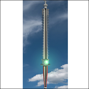
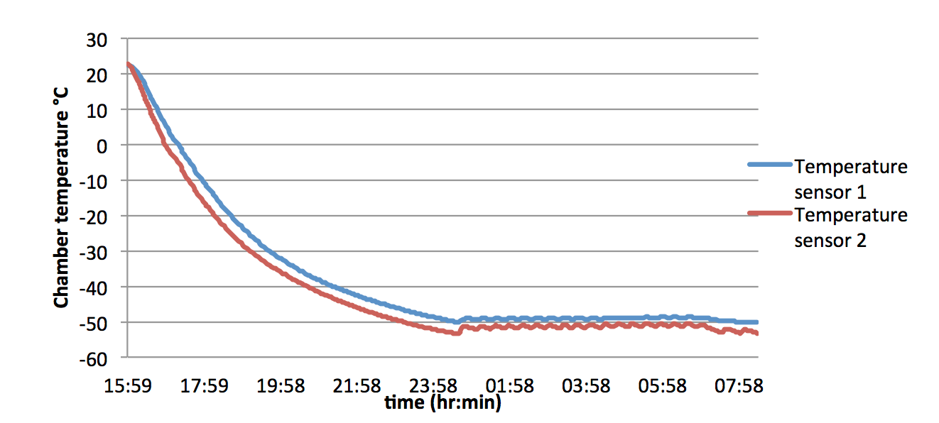
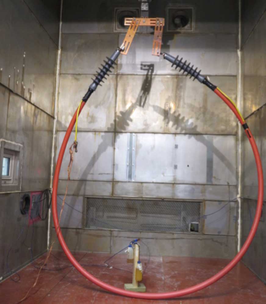
Many TSOs these days that equipment supplied to them be tested to assess performance under extreme temperatures down to -50°C or even -60°C. A climate chamber equipped with a bushing enables high voltage tests such as AC, DC or impulse testing under these extreme cold conditions. Partial discharges can also be measured. For example, impulse and AC testing were performed on medium voltage cables and cable accessories at -50°C. Temperature was reduced to -50°C and held there for 8 to 12 hours, depending on customer specification, after which the AC or impulse test was performed (see Fig. 3). In some cases, a ‘dummy’ cable with temperature sensors is placed near the test cable in order to compare core temperatures in the cable conductor. Fig. 4 shows an example of a cable being tested at low temperatures in a climate chamber.
Dielectric Tests
Long Term Testing of HV Equipment
A manufacturer of high voltage equipment wanted to investigate how their product would withstand long-term exposure to an AC voltage superimposed on a DC voltage. A special outdoor test circuit was designed for this purpose, equipped with test transformer and rectifying circuit. The equipment, designed for 245 kV, was tested for 22 months at elevated voltage during which leakage current and partial discharges were measured.
Rapid Flashover
Testing HV equipment for different service conditions can be time consuming and costly, especially if it requires testing under different levels of contamination to yield a pollution performance curve. For this reason, STRI developed a rapid flashover method modelled on the principle of applying pollution to an insulator followed by application of voltage. If the insulator withstands the voltage level, voltage is increased to flashover at the end of the test.
Impulse Test After One Year Pre-qualification Test on HVDC Cable
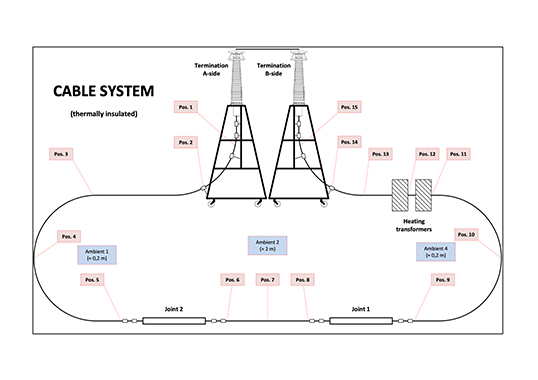
After performing the 1-year pre-qualification test, guidelines from CIGRE require that superimposed impulse testing be conducted on a 30 m section of cable. The special requirement of one customer, however, was that the complete 120 m cable system, with all accessories, be tested. Applying superimposed impulses on DC-voltage for a full-length cable system places extremely high requirements on the test circuit as well as on individual components such as the DC-generator and impulse generator (see Fig. 5). Superimposed lightning and switching impulses were then successfully performed. In the case of lightning impulses, it is not possible to fulfil the requirements in the standard in regard to front time. In fact, CIGRE has now begun updating Technical Brochures regarding cable testing such that requirements on front time will be changed to a higher value than what is specified in IEC 60060-1.
Effects of Electric & Magnetic Fields
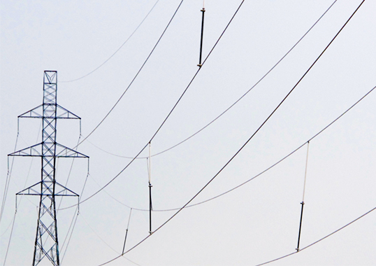
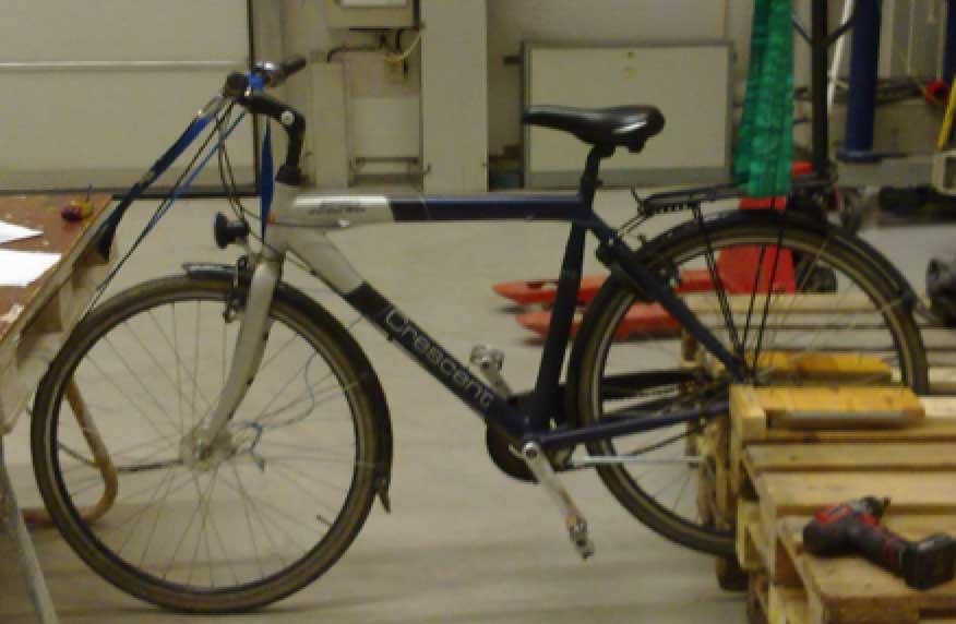
TSOs sometimes receive complaints from the public regarding effects of electric and magnetic fields around power lines. One issue, for example, has involved activities such as bicycling and riding horses near lines. To investigate whether riding a bike under power lines can be an issue, STRI was asked to simulate this with an experiment and measurements. First of all, actual electric fields were measured under a 400 kV power line and results showed an enhancement of electric field by 50% when bicycling under the line. Based on this, the energy in a possible discharge was estimated as 1.1 mJ – a level that, while without real danger, could nonetheless be felt. Still, these measurements could not explain some of the phenomena experienced in the field. One possible explanation could be type of clothes being worn. To simulate this, a test engineer cycled with different clothes to evaluate possible difference between synthetic and cotton materials. The contribution to discharge energy from static charging of clothes can roughly be 0.5 mJ which, if added to the 1.1 mJ, would yield a clear increase. The influence of clothes was that cotton gave a positive electric field and synthetics a negative field. In addition, influence of magnetic and electric fields on equipment working around energized lines was also evaluated. Lifting insulator strings with a helicopter, for example, could potentially be an issue when working in and around energized lines. This was simulated by lifting a hook with a crane while, at the same time, exposing it to different electric and magnetic fields.
Temperature Rise Testing at Elevated Temperatures
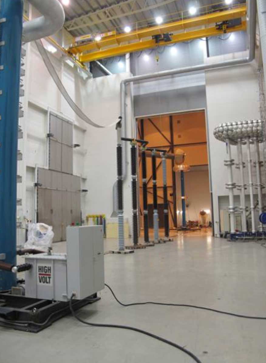
Some customers, such as from China, require that bushings be tested in a test hall with 50°C ambient temperature. One of the test halls at STRI used for temperature rise testing is able to perform such tests at elevated temperature. Recently, an ABB wall bushing rated for 1100 kV DC was tested at +50°C ambient temperature and current of 5839A DC. Similarly, a wall bushing was tested with +45°C on the outdoor side and +60°C on the indoor side. Such conditions place high requirements not only on the test equipment (in this case installed at +45°C) but also on testing staff.
Summary
Requests for non-standardized tests are coming both from specific user requirements (e.g. service environment, system, etc.) and the fact that many standards are not up-to-date and have to be revised to reflect more stringent conditions. These types of tests impose high requirements on test equipment that needs to be easily moved around as well as on skills of test engineers.
References
1. Berlijn, S, Halsan, K, Gutman, I, Summarising knowledge from laboratory ice and snow tests on glass and composite insulators for overhead lines, Proceedings of the 15th international workshop on atmospheric icing of structures (IWAIS XV), St. Johns, NL, Canada, September 8-11, 2013
2. https://sverigesradio.se/diverse/appdata/isidor/files/159/9c96b755-644d-486f-8bca-3a74613b8e68.pdf

