Station post insulators are indispensable for substations as well as HV apparatus. Classic technologies are ceramic (i.e. glass and porcelain) designs applied for more than 100 years. Such products are established and well standardized in testing and selection process. Since the 1980s, however, application of composite station post insulators has been growing steadily.
This edited contribution to INMR by Matthias Domm, Andreas Baumer and Jens Seifert of Reinhausen Power Composites reviews state-of-the-art post insulator technology, related standards and applications for station post insulators – both in general and specifically for hollow composite station post insulators with foam filling. It also provides an outlook for future applications where use of foam-filled composite insulators may become the preferred choice.
Types of Station Post Insulators
There are several different types of station post insulators, depending on application:
1. Porcelain Station Posts
Porcelain station post insulators in the range 1 to 765 (800) kV have been applied at substations for over a century. Maximum cantilever strength classes are in the range of 20 to 30 kN. Single units can be manufactured up to a length of 3000 mm. For voltages exceeding 245 kV, multi-unit stacks consist of a minimum of two individual units connected by metal flanges.
IEC standard 60273 is applicable for selecting IEC type station posts according to their characteristic values and IEC 60168 is the corresponding test standard. Post insulators, according to ANSI standard C29.9, are defined as ‘catalogue’ (TR) types according to their characteristic values and the range covered is up to 765 kV. ANSI C29.9 also defines applicable test requirements.
Porcelain station posts, in accordance with IEC 60273 and ANSI C29.9, are both well defined and can be ordered according to the applicable C- or TR-code respectively. Still, these standards are viewed as outdated and in need of revision to accommodate the latest technological changes as well as the updated definitions of the pollution classes, as found in IEC 60815-2.
Modern production technologies enable high-strength designs optimized in shape, weight and shed profile. For applications under severe pollution, RTV silicone coatings can be applied to improve electrical performance.
2. Glass Station Posts
Glass station posts, also specified in IEC 60273, consist of individual units made of glass discs typically assembled using cement. This enables complex housing profiles. While application of multi-unit glass stacked post insulators at modern substations is rare, many such installations still exist from the 1950s and 60s. For applications under severe pollution conditions, RTV silicone coatings can also be used to improve electrical performance.

3. Hybrid Station Posts (HSP)
Hybrid station posts, according to IEC TR 62896, are combinations of porcelain (ceramic) and polymer technology. The core is usually made of solid high-strength porcelain material (i.e. a C130 body) while the housing consists of an elastomer such as liquid silicone rubber (LSR) or a high-temperature vulcanized (HTV) silicone material that has been applied over the porcelain by injection molding or extrusion. The advantage of HSPs comes from the low deflections of their rigid porcelain core with high E-modulus under cantilever load in combination with a hydrophobic silicone housing that improves electrical properties under polluted conditions. Applications include large HVDC post installations as well as posts for disconnector switches which require low deflection.
4. Solid Core Composite Station Posts (CSP)
With development of composite insulators, the first CSPs introduced in the early 1980s consisted of a solid fiber-reinforced (FRP) core and an elastomeric housing. Typical FRP core diameters in this type of station post fall in the range of 45 to 100 mm and maximum diameters rarely exceed 130 mm.
Application at substations initially derived from early use as composite line post (CLP) insulators, mainly in the United States. CSPs with solid core are typically applied up to 245 (420) kV. For higher voltage classes, their relatively high mechanical deflection limits broader application. The test standard for this product is IEC 62231 while the mechanical and electrical characteristics are defined in IEC 62231-1 (which also includes the ANSI types used in North America). ANSI C29.19 is the relevant standard.
5. Composite Hollow Core Station Posts (CHSP) Filled with Foam/Gas
For voltage classes greater than 245 kV, both height and bending moment of the station post increase. Greater effort must therefore be made to realize these requirements using solid core CSP designs (i.e., with core diameters > 170 mm) and this leads to typically less economical designs compared to porcelain.
Composite hollow core station posts (CHSPs) and hybrid station post (HSP) insulators tend to occupy this segment of the application portfolio. CHSPs have already been developed for 800 kV HVDC and 1100 kV UHV applications with connection lengths of more than 10 m and tube diameters of 500 to 1000 mm. Bending moments of more than 1000 kNm then become feasible. To ensure that no moisture or conductive contamination can penetrate the hollow volume inside the posts during their service life, these must be filled with an electrically inert medium such as foam or insulating gas. The corresponding test standard is IEC 62772.
Filling the internal volume of a CHSP with foam results in a foam-filled station post (FFSP). FFSP type post insulators are made of high-strength glass fiber-reinforced polymer (GRFP) tubes, corrosion resistant flanges and tracking/erosion resistant silicone housings for superior pollution performance and to fulfill all quality requirements of today’s power grids. Typically, the foam consists of polyurethane in combination with an insulation gas that seals the inside of the insulator.
In contrast to foam-filled CHSPs, gas-filled types require an additional pressure monitoring system to verify that the insulator remains properly sealed. The main insulating gas used in gas-filled a CHSP is still SF6, in spite of it being recognized as a greenhouse gas with a very high CO2-equivalent. Efforts are currently underway to replace SF6 with a more environmentally friendly insulation gas.
This type of filled station post design allows for light weight combined with high cantilever strength which make them especially well-suited for application in seismic areas. In fact, properly manufactured CHSPs can meet the stiffness of specific porcelain types according to IEC 60273 or ANSI C29.19 values. Moreover, voltage classes can be realized up to 1100 kV using a single unit design. For special applications, these insulators can also be equipped with non-magnetic GFRP flanges.

Applications
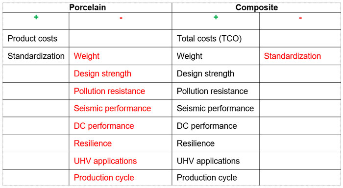
Table 1 shows the application spectrum of the different station post insulator technologies. The widest range is covered by standard solid core porcelain insulators (mostly without RTV coatings) and their application is regarded as state-of-the-art for most voltage classes including 800 kV. Nonetheless, a maximum feasible solid core diameter of 300 mm is a limiting factor in cantilever strength. Moreover, their high weight limits use in applications exposed to seismic stresses. While use of RTV coatings enables improved pollution behavior, it also significantly increases total cost and makes handling, transport and installation more challenging.
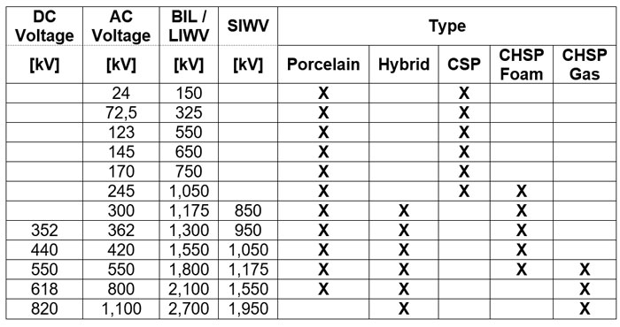
Composite post insulators offer advantages compared to porcelain due to lower weight as well as better seismic performance, pollution resistance and resilience. CSP type insulators are used up to 245 kV while for higher voltage classes the CHSP type is preferred, especially since there are almost no limitations in single unit length and diameter. Indeed, FRP tube diameters of more than 1000 mm are already in service. Solid media (e.g. foam) filled CHSPs tend to be applied in the medium voltage segment while the upper end (i.e. > 550 kV) is typically filled with insulating gas for lower weight and material costs.
Applications for station post insulators at substations include:
• Bus bar supports (substations);
• Disconnector switches;
• HVDC converters;
• FACTS / platforms (UPFC, SVC, capacitive and reactive compensators);
• Coil supports;
• Optical CT/VT supports;
• Optical fiber bushings (station post type).
For example, CHSP insulators with a length of 10 m and 580 mm tube diameter are used in coil support insulators at HVDC converter substations. The CHSPs for this application are filled with gas under pressure in accordance with IEC 62772 and gas pressure is controlled and monitored. Another application for gas-filled CHSPs is in UHV disconnector switches.
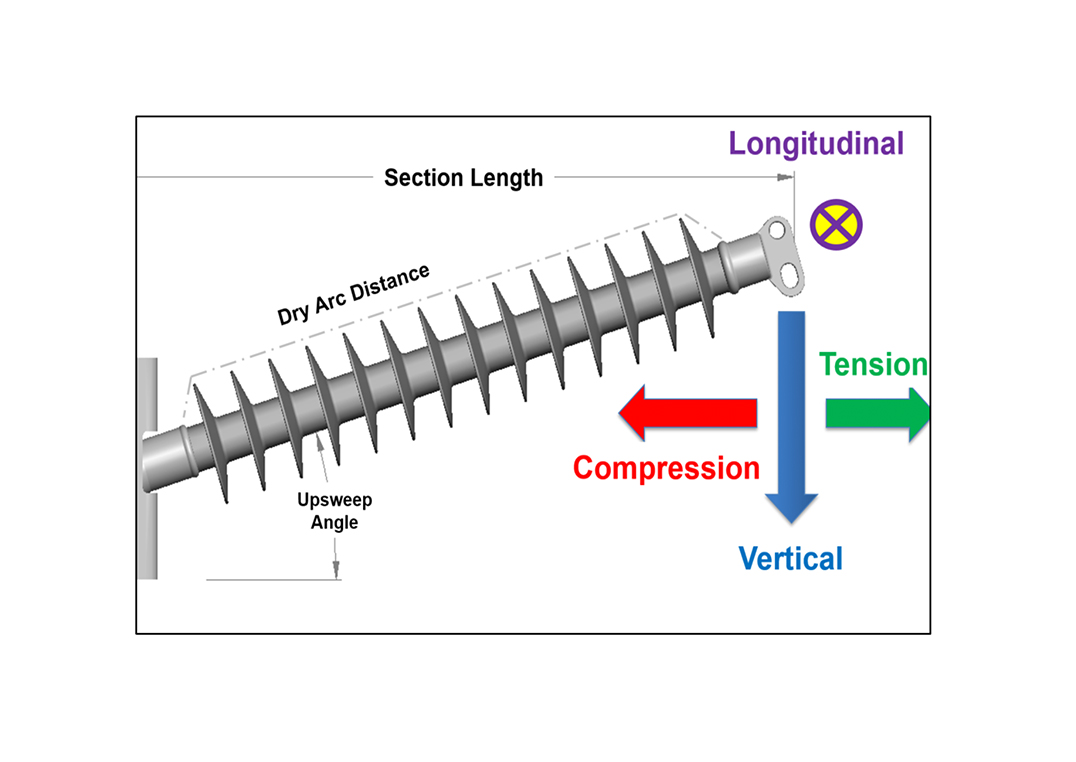
The main mechanical load of station posts depends on application and can be either bending, torsion, tension or compression. In the case of coil supports, the main load is compression. CHSPs are preferred for this application because of their superior mechanical one-unit design along with excellent insulation performance of the hydrophobic silicone under pollution and DC voltage stress.
Another driver toward greater application of CSPs and CHSPs comes from their superior seismic resistance. Finite element simulations that consider static and dynamic damping characteristic properties have to be performed to assess theoretical seismic performance. The design process is then run interactively considering weight, strength and damping of the entire assembly. To reach a final design solution, most customers also require shaker table tests to simulate real conditions. While such test efforts can be intense, the process can be made significantly easier if composite station posts are used since they are not brittle, show high self-damping properties and can be designed with high strength at low weight. Table 2 summarizes the relative advantages and disadvantages of composite station posts compared to porcelain types.

Foam-Filled Station Posts
1. Requirements
Foam-filled station posts must fulfill several requirements, the most important of which include:
• High mechanical strength;
• Single unit design for HVDC and EHV (500 kV and above);
• Long-term moisture protection of the hollow internal volume, without need for monitoring;
• No ageing of internal filling media;
• Robust and sustainable product and process technology;
• Accommodation of high creepage factors;
• Resistance against seismic shocks and vandalism;
• No use of greenhouse gases such as SF6.
2. Production Technologies
The GFRP tube of FFSP type insulators is manufactured mainly by the wet filament winding process.
There are two different industrial production technologies to apply the silicone housing, i.e. LSR / HTV injection molding and HTV extrusion (see Fig. 1).
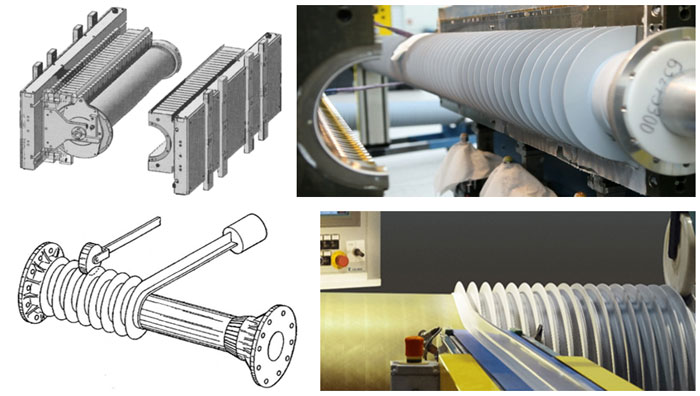
Injection molding technology is mold based and preferred for large volume production of a single insulator type. Single shot lengths are typically in the range of up to 3000 mm but design flexibility is less than with extrusion technology which offers a spectrum of different possible shapes (e.g. conical) and shed profiles with less tooling and set-up effort (see Fig. 2). ‘Modular’ technology which involves assembly of individual sheds is also used, but mostly for low volume production (e.g. specialty insulators).
Silicone rubber housings are deemed superior due to their surface hydrophobicity and the ability to transfer this property to the pollution layer through a hydrophobicity transfer mechanism (HTM). Composite and hybrid station posts (and also RTV silicone coated porcelain post insulators) are more resistant to pollution flashover, especially under DC voltage stress. Apart from offering HTM, tracking and erosion resistance is another important property of the silicone housing. HTV housing materials offer superior performance at AC and particularly under DC voltage stress.
3. Foam-Filling
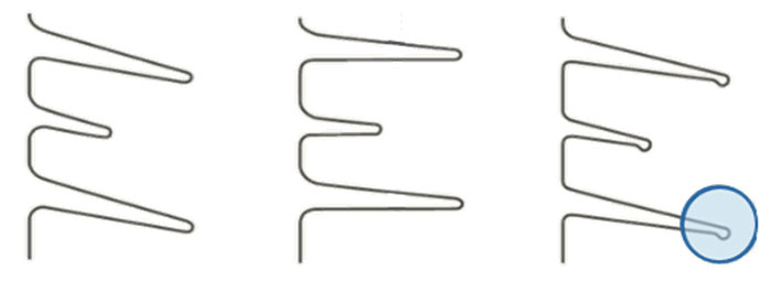
Keeping moisture out of the internal volume of a composite hollow station post is the top priority in design to ensure good electrical performance and reliable insulation properties. The core element of a composite hollow insulator is the GFRP-tube with a moisture vapor transmission rate (MVTR) greater than zero. As in any physical system in non-equilibrium, the direction of vapor transmission follows the gradient of saturation of the inside and outside of the insulator (see Fig. 3).
Insulator applications with a current-carrying conductor on the inside (e.g. bushings, cable terminations, etc.) benefit from the internal heating effect which reduces or even reverses the moisture vapor transmission gradient. Moreover, drying technologies are integrated into applications with gas-filled insulators and this helps manage moisture ingress. Station post insulators, however, are passive applications without ‘internal heating’ and this makes it essential to handle any moisture inside the insulator.
In most applications, station post insulators are installed outdoors and often must perform under harsh environmental influences, including temperature fluctuations, UV radiation, pollution, wind, humidity, etc.). In particular, influence of moisture on insulator function must be investigated since it cannot be avoided in outdoor applications. In the case of gas-filled insulators, there is risk due to temperature changes as the dew point is reached and condensation occurs. This could lead to outage of the entire insulation system. No matter what filling technology is used, influence of moisture ingress must be considered since it could impact HV design properties (e.g. breakdown strength, dielectric loss factor).
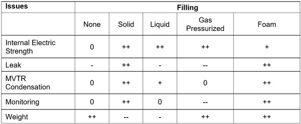
Table 3 offers a general assessment and comparison of different filling technologies. Key points to consider:
• No Filling
A simple methodology but greatly influenced by environmental conditions at the manufacturing site (e.g. high humidity, rapid condensation during temperature changes).
• Solid Filling
Positive rating, but heavy weight.
• Liquid Filling
As for solid but leaking and potential monitoring can be critical.
• Gas Filling (Pressurized)
As for liquid, there are monitoring and potential leakage issues; handling condensation with desiccant application.
• Polyurethane (PU) Foam Filling
Good sealing of inner volume and bonding to GFRP tube; density around 0.4 g/cm3; consistently positive assessment.
• Dry Syntactic Foam (DSF) Filling
Microspheres; innovation regarding low density (0.1 g/cm3); no chemical technology; high dielectric strength; but limited-service experience.
Polyurethane foam has been the subject of research in the HV industry for many years now. For example, qualification tests for PU foam as a filling material have resulted in a breakdown strength of 3 – 4 kV/mm (AC RMS) for round plate configurations with sample thickness of 6.5 to 10 mm. Performance can be improved using special formulated foams.
In addition to chemical PU foam, Dry Syntactic Foam (DSF) is an option for light weight hollow filling with an insulating medium of high electrical breakdown strength.
The electrical and dielectric properties of DSF depend greatly on density and were studied extensively in several research projects (see Fig. 4).
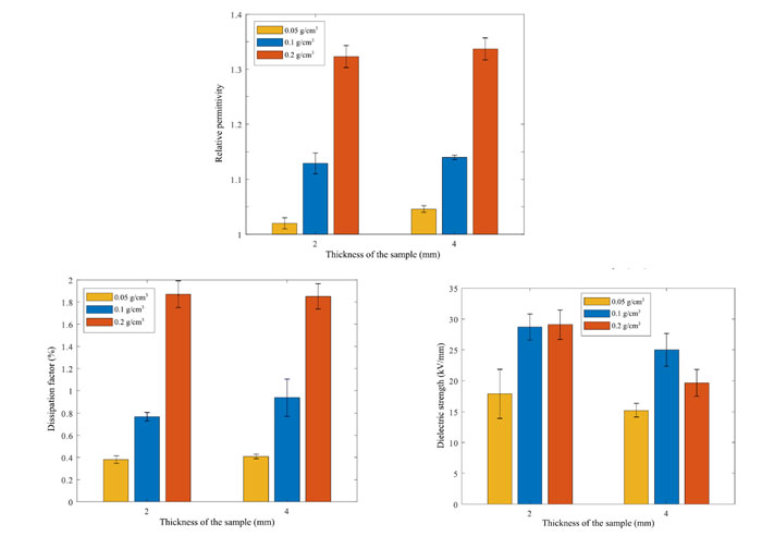
DSF filling can be realized by means of a thermal heating process if mixtures of thermal expandable and non-expandable microspheres are applied. Target density can be controlled by the ratio of the different grades of microspheres as well as temperature profile during the process.
DSF technology looks promising but challenges such as heat transfer/flow during the process need to be resolved, especially for large diameter hollow insulators.
4. Applications
Fig. 5 shows new apparatus using optical technology to measure voltage and current (optical CT/VT). The basic technology is opto-electronic equipment, usually accommodated in the head or inside a hollow post insulator. Here, the hollow composite station post insulator acts as mechanical support carrying the measuring device with connected conductor and acts as insulating bushing for the optical fiber that is led through the hollow core. Typically, the internal hollow volume is filled with an insulation foam or jelly or, in rare cases, with gas. Composite insulators dominate this market due to their above-mentioned superior properties.
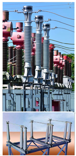
An innovative design for a 3-phase 362 kV disconnector for application in seismic and high pollution environments is also shown in Fig. 5 (bottom). Availability of CHSPs is the key factor that enables design of such new apparatus. A conically- shaped insulator was chosen due to low weight as well as superior mechanical and pollution performance. In such cases, the total cost of ownership (TCO), considering LCC, maintenance, need for washing, resilience against terrorism, vandalism, seismic, is more and more the decisive factor behind product selection.
A new potential field for foam-filled composite hollow core insulators are compact power pylons. The change to renewable energies as well as increasing electricity consumption are placing greater demands on power grids. However, long approval processes and resistance from the public often complicate necessary grid expansion. Therefore, an EU-funded project was carried out between 2019 and 2022 with the goal of developing a compact power pylon with low environmental impact.
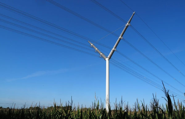
The main idea behind the European Composite Power Pylon is that the arms carrying the conductors are made of composite hollow core insulators. As such no long rod insulators are needed and this results in significant height reduction of the pylon, i.e. 30 m compared to 64 m for a conventional 2 x 400 kV lattice tower. Use of a solid mast also reduces structure footprint from 64 to only 1.5 m2. Moreover, the easy design allows assembly of at least 2 pylons a day whereas a conventional lattice tower requires a week to assemble a single pylon. As part of this project, three full-scale 2 x 400 kV demonstration power pylons have been produced and assembled in Denmark (see Fig. 6).
However, the insulating arms of the European Composite Pylon must be sealed for the same reasons as discussed above for most substation insulators. To avoid need for pressure monitoring, it would be beneficial to fill these hollow core insulators with foam. In a 400 kV pylon, each arm has a length of 16 m resulting in a large inner volume to fill. Use of Dry Syntactic Foam has therefore been investigated for this application to lower material costs and weight.
Trends, Challenges & Conclusions
Porcelain and composite insulator technology for station post insulators is now mature. The main advantages of composite station post insulators include:
• lightweight design;
• high strength;
• superior pollution resistance (hydrophobic surfaces);
• large design and manufacturing freedom;
• applicable for voltage classes exceeding 420 kV and for 800 kV HVDC and 1200 kV UHV.
Hollow station post insulators enable design of new optical fiber bushings and optical CT/VT applications. Also, special new insulating flanges are entering the market, especially for anti-magnetic coupling parts. Concerns regarding expectation of service life have been resolved by long-term service experience of more than 35 years. But a remaining challenge is to define tests that secure stable, service proven designs and distinguish these from cost-optimized ‘cheap’ solutions that may compromise lifetime and quality expectations. The latter could give this technology a negative reputation.
Future development steps for CHSPs include standardization work for the full portfolio of composite station posts, e.g. completion of standards for characteristics in both IEC and ANSI. In ANSI, the TR types are still missing and in IEC the range above 245 kV has not yet been standardized in regard to characteristic types.
Compared to gas-filled CHSPs, foam-filled units have the advantage that no pressure monitoring and use of greenhouse gases are needed over their lifetime. But challenges remain for bigger dimensions with large inner volumes due to higher material costs and weight. However, there is potential in regard to economic and ecological media to fill large volumes. Related R&D work is underway.
Over the next 20 years, FFSP insulators will likely replace conventional insulators in most if not all industrial solutions. They may also open new fields (such as compact power pylons) due to economic and technical advantages that consider a TCO model that includes initial costs, supply chain, environmental influence, maintenance, lifetime and risk assumptions.
REFERENCES
[1] IEC 60273:1990. Characteristic of indoor and outdoor post insulators for systems with nominal voltages greater than 1.000 V;
[2] IEC 60168:1994+AMD1:1997+AMD2:2000 CSV
Consolidated version. Tests on indoor and outdoor post insulators of ceramic material or glass for systems with nominal voltages greater than 1.000 V;
[3] ANSI C29.9:1983. Wet process porcelain – apparatus, Post Type.
[4] IEC 60815-2:2008. Selection and dimensioning of high-voltage insulators intended for use in polluted conditions. Part 2: Ceramic and glass insulators for AC systems.
[5] IEC 61952:2008. Insulators for overhead lines – Composite line post insulators for AC systems with a nominal voltage greater than 1.000 V – Definitions, test methods and acceptance criteria.
[6] IEC 62231:2006. Composite station post insulators for substations with AC voltages greater than 1.000 V up to 245 kV – Definitions, test methods and acceptance criteria.
[7] IEC 62231-1:2015. Composite station post insulators for substations with AC voltages greater than 1.000 V up to 245 kV – Part 1: Dimensional, mechanical, and electrical characteristics.
[8] ANSI C29.19:2020. Composite station post insulators.
[9] IEC 62772:2016. Composite hollow core station post insulators for substations with AC voltage greater than 1.000 V and DC voltage greater than 1.500 V – Definitions, test methods and acceptance criteria.
[10] IEC TS 62896:2015. Hybrid insulators for AC and DC high-voltage applications – Definitions, test methods and acceptance criteria.
[11] www.reinhausen.com
[12] J. M. Seifert, D. Stefanini; „Pollution resistant composite insulators”, ICHVE 2008, Chonqing, China, 2008.
[13] J. Kindersberger, M. Kuhl, “Effect of hydrophobicity on insulator ferformance“, 6th ISH, New Orleans, 1989;
[14] R. Strobl, P. Stahl; “Station post insulators (SPI), An emerging application for composite hollow core insulators”, Proceedings of INMR Congress, Munich, 2015.
[15] U. Fromm et al., “Electric field control by polymer foam,” in 1998 IEEE 6th International Conference on Conduction and Breakdown in Solid Dielectrics, Vasteras, Sweden, Jun. 1998, pp. 460 – 463.
[16] A. Mashkin, A. Strauchs, A. Schnettler, J. Podlazly, and K.-M. Ress, “Investigation on inverse volume effect of syntactic foam under uniform dc field stress,” in Conference record of the 2010 IEEE International Symposium on Electrical Insulation (ISEI): 6. – 9. June 2010.
[17] D. Machetti, E. Moal, J.M. Seifert, R. Puffer; “Electrical characterization of low-density solid insulating fillers for hollow-core composite insulators”, Proceedings of the ISCD 2020.
[18] H. Skouboe, E. Frederiksen, J. Brocard, S. Morice, M. Domm, “2×400 kV composite pylon ready for use, innovative and compact – reducing the impact of OHTL considerably”, CIGRE B2 Overhead Lines, PS3 Environmental and Safety Aspects from OHL, ID 10889, Session 2022 .
[19] M. Domm, J. Seifert, V. Bergmann; “Development and feasibility analysis of insulation support arms for compact power pylons”, Proceedings of ETG-Fb. 169: VDE Hochspannungstechnik 2022.