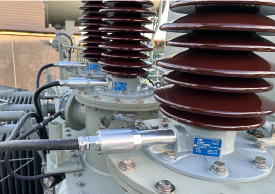
Mexico’s power system operator, the Comisión Federal de Electricidad (CFE) relies on more than 470 substations with a total of circa 2700 power transformers from 115 kV to 400 kV. Most of these are equipped with oil impregnated paper bushings (OIP) while there is lesser use of resin bonded paper (RBP) bushings as well as resin impregnated paper (RIP) bushings. Operating experience has demonstrated that more than a quarter of all transformer failures (27.7%) are due to failed bushings, about half the time with catastrophic results.
This edited 2015 contribution to INMR by the late Manuel Guzmán V. and Fernando Elizarraz R. of LAPEM and Ricardo Montes F. of the CFE, discussed the utility’s experience mainly with OIP HV bushings retired from service for diagnostics, maintenance or failure analysis.
Due to growing commercial and industrial activity in Mexico, electricity demand is increasing by about 5% per year. The CFE operates a grid covering 9 different Regions. This network is comprised of more than 57,000 km of overhead transmission lines and some 470 substations with nominal voltages of 115 kV, 161 kV, 230 kV and 400 kV and where a total of 2760 power transformers equipped with 6500 HV bushings are in service.
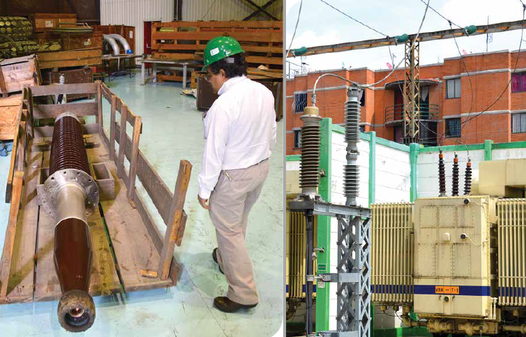
CLICK TO ENLARGE
Analysis of power transformer accidents between 2000 and 2014 has demonstrated that bushings are often the ‘weakest link in the chain’ and also the second leading cause of such failures (see Fig.2). Indeed, historical data shows that 27.7% of all power transformer failures in Mexico were due directly to problems with the bushings.
Moreover, statistics reveal that 400 kV bushings account for the highest proportion of such failures, amounting to 50% over the 15 year period studied. It is also important to note that, since the CFE’s main transmission grid is spread over Mexico at 400 kV, recovery time becomes an important issue in maintaining a service level with a high standard of quality and reliability.

CLICK TO ENLARGE
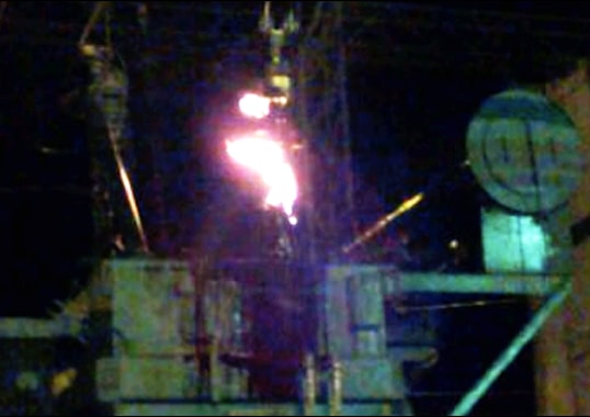
Another important issue is that of all power transformer failures due to issues with bushings, 53% had the catastrophic result of the transformers burning. Moreover, analysis shows that failures of power transformers from 2000 to 2014 due to bushing problems carried a high cost because a total of 114 MVA was disconnected from the grid, even without consideration of the downtime needed for servicing, the cost of repair or replacement of the bushings or the cost of cranes, materials and manpower needed to restore service to the affected transformer.
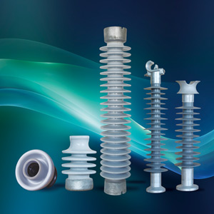
Past studies within the CFE have shown that polymerichoused bushings are an attractive option for polluted and/or seismically active service areas because of their inherent surface hydrophobicity, light weight, easier handling and superior mechanical stability with more resistance to bending motion. There is also no risk from explosive failures that, in the case of ceramic-housed bushings, could see high velocity shards of porcelain ejected onto adjacent equipment.

CLICK TO ENLARGE
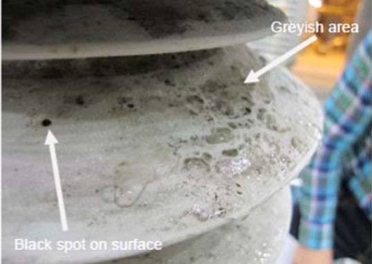
However, notwithstanding these benefits, there have been some reported problems related to differences in formulation of the silicone rubber material, different manufacturing processes and different laboratory test methodologies to evaluate these parameters.
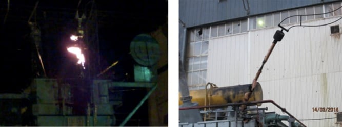
CLICK TO ENLARGE
Technical Reference for Laboratory Testing
The CFE’s technical specification for power transformers allows the manufacturer to select suitable bushings based on technical requirements and design. At the same time, this technical specification is based on IEC 60137 and lists the main requirements that must be fulfilled for HV bushings installed on power transformers. This standard indicates the bushing reference values for testing performed on C1 at laboratory facilities, i.e.:
• Tan δ of 0.007
• Max Δ tan δ 0.001 for OIP (at Um & 1.05Um/√3)
• Partial discharges of 10 pC @ Um and 5 pC @ 1.05Um/√3
The experiences show us that for Tan δ, most of the manufacturers have lower values.
Tan δ ≤ 0.005 for OIP.
In the diagnostic process the above values are used only as reference. A technique that combines several tests is then applied, such as measuring C1, tan δ (before and after), power frequency (80 to 85%), testing withstand voltage and measuring partial discharges. There are no tests specified for the insulating oil.
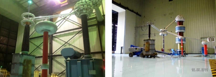
CLICK TO ENLARGE

CLICK TO ENLARGE
The CFE substation manual recommends conducting diagnostic tests on bushings under the following circumstances:
• Loss of oil level;
• Failure occurring on the power transformer;
• If one of the other two bushings fails (for 3-phase power transformers);
• If a bushing has been stored for years but needs to be installed as a spare;
• If the results of on-site testing of power factor is high;
• When a power transformer is being repaired and it is necessary to verify the condition of existing bushings;
• After a severe earthquake or short circuit on the power transformer;
• Whenever a bushing is removed from a power transformer because it is to be relocated to another substation;
• In order to prevent failure at the end of its useful service life;
• Whenever a bushing has been refurbished.
Is necessary to have exact diagnostic for all cases listed above, in order to have the power transformer in excellent conditions before re-energize it.
Technical Reference for On-Site Testing
Taking into account past engineering experience, the advice of technical experts and recommendations from industry groups, CFE has developed its own procedure for on-site testing of bushings. This technical document is a substation maintenance manual named “Manual de Transformadores y Reactores de potencia, Tomo I y Tomo II, junio 2007” and is also referenced in CFE’s Technical Specification.
Reference values for on-site testing are:
• FP: Up to 0.5% at 20 C.
• C1: ± 2% of original value
• C2: ± 2% of original value
In certain cases where there is not sufficient data from testing on site, a dielectric spectroscopy test could provide more information about the condition of the insulation as well as its humidity content. Results from this test could provide valuable in helping decide whether a bushing can be safely installed or not.
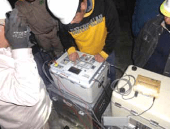
CLICK TO ENLARGE
Findings from Laboratory Testing
Laboratory tests allow a good indication of the condition of a bushing but for an effective analysis it is important to keep in mind the time of operation and the standard of reference values. The most common findings during such tests in the lab are:
• The bushing presents changes in C1 as well as values for tan δ;
• There is a fault (perforation) during the power frequency withstand test; and
• Values of partial discharges recorded fall from 50 pC to as high as 500 pC.
All these results taken either alone or in combination allow a suitable assessment of condition, e.g. if the bushing being tested has DP values near to 100 pC and if tan δ values are near to 0.008 but the C1 and power frequency withstand test show good results, then re-generation of the insulating oil and subsequent retesting is recommended.
Findings During On-Site Testing
The maintenance period on transformers is 2 years and in this case the most common test results between sequential maintenance cycles are:
• Power Factor differences of up to 1%;
• Exponential differences in C1 measurements due to degradation of foils;
• Corrosion on capacitive tap connections to the outside, leading to improper connections;
• Movement of the porcelain housing from the flange (verified by visual inspection).
Typical Failed Components on Bushings
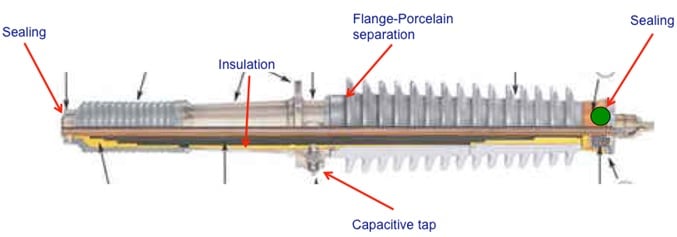
Fig. 5 depicts the components within a bushing that experience in Mexico suggests most commonly contribute to failure. These depend not only on period of operation but also on environmental factors of the area where the unit is in service. For example, if a bushing is installed near the coast and seal parts show incipient failure, there could be humidity in the internal insulation or corrosion in the C1 tap.
CLICK TO ENLARGE
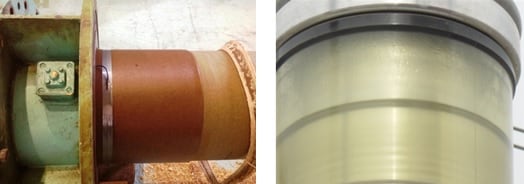
Degradation of Seal & Moisture Ingress
This usually depends on the operating time of the power transformer or/and climatic variables that lead to loss of flexibility in the seal due to frequent changes in temperature. The result is that moisture can permeate into the bushing or there will be leaking oil.
CLICK TO ENLARGE
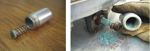
Corrosion on Capacitive Tap Materials
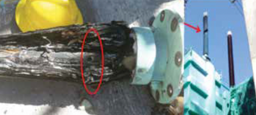
Such failure is most common on bushings installed in coastal areas where they are most exposed to risk of corrosion. Since this connection is considered one of the weakest parts of a bushing, any such corrosion could start a process that culminates in catastrophic failure.
CLICK TO ENLARGE
In many cases, the cost of spares is high and most suppliers have a fairly long delivery lead-time. If a bad connection remains undetected, results could soon be catastrophic.
Degradation of Capacitive Foil
Ageing of insulating material or moisture ingress will cause degradation of the oil and paper insulation. This will increase partial discharge activity and modify the original values of Tan δ and could lead to catastrophic failure. While it is possible that risk of failure during power frequency testing may be high, it is preferable that failure occurs during the test and not while the bushing is in service.
Flange-Porcelain Separation
This kind of failure usually occurs during earthquakes or due to the high forces from an external flashover. Any such displacement between porcelain and flange allows moisture ingress and the bushing will need to be repaired.

Bushing Repair
In order to restore the power transformer to operation in as short a time as possible, especially and if there are no spares to replace the one that failed, a common practice within the CFE is to try to repair the bushing. This work includes:
• Repairing the connection, installing and sealing of C1 tap;
• Regenerating or replacing the insulating oil;
• Drying the various insulating parts;
• Re-tightening of flanges, connectors and bushing terminals;
• Rewinding the top paper foils but without modifying the capacitive foils;
• Re-aligning the porcelain hollow core insulator and the flange;
• Re-sealing the sections between porcelain and flange;
• Conducting minor repairs on external porcelain parts.
• Restoring oil level recovery.
The C1, by contrast, is not repaired.
After bushing repair, a diagnostic test routine is performed. If the test results are satisfactory, according with criteria discussed before, the bushing is placed back in service.
Areas Where Work Remains on Standards
• The CFE bases its technical specification for bushings on the IEC standard and the latest edition takes flange dimensions from the ANSI standard.
• It is necessary to add a technical criterion in regard to a C1 increase that may indicate incipient failure (1% every 5 years).
• There are no technical criteria that consider increases in tan δ (as per the standard for CTs).
• A sampling valve to test insulating oil may be necessary.
• The IEC standard does not include flange dimensions.
Summary
The bushing is a power transformer accessory that plays a major role in contributing to equipment failure. It is therefore important to have a range of diagnostic tools available to prevent such failure. It is also important to have experience in bushing refurbishment and testing as both will prove helpful in keeping the time for bushing recovery as short as possible.
Depending on the relative importance of any transformer, high voltage diagnostic tests are carried out on site, mainly at 400 kV and above. This eliminates risk of damage from moving test objects to distant laboratory facilities.
On-line monitoring systems have not yet been shown to be effective in all cases as there remain doubts about their operation and performance in service. Moreover, some monitoring systems have been known to cause rather than prevent failures of power transformers. Bushing refurbishment has proven to be a good technical and economic option to quickly re-energize a power transformer and is especially interesting when it is not possible to buy a new one in a short time.

