Cap & pin type porcelain insulators that were removed after 25-30 years in the field were evaluated in the past with the goal of assessing the condition and performance of those insulators remaining in service. Some of these units failed the puncture test and were cut open for analysis. Electric field due to the presence of microscopic defects in porcelain was modeled using a 3-D software package.
This edited past INMR article contributed by Dr. Ravi Gorur, then at Arizona State University, showed that local electric field enhancement can be high enough to cause dielectric breakdown of the porcelain. Electrical deterioration is a slow process. The breakdown process creates phase changes in the porcelain microstructure and this was confirmed using a scanning electron microscope.


Many insulators in service today are either reaching or have already crossed the threshold of their expected operational lifetime of 30 years. Therefore, to maintain transmission system reliability, electric power companies need to be able to determine if these insulators are more at risk of failure and, if so, replace them in a timely manner. Moreover, many existing contracts for power delivery are such that, in order to avoid heavy penalties, maintenance must be done without taking the line out of service. Therefore it is now critical to perform such assessment (and any other related work) on the transmission network under energized (i.e. live) conditions.
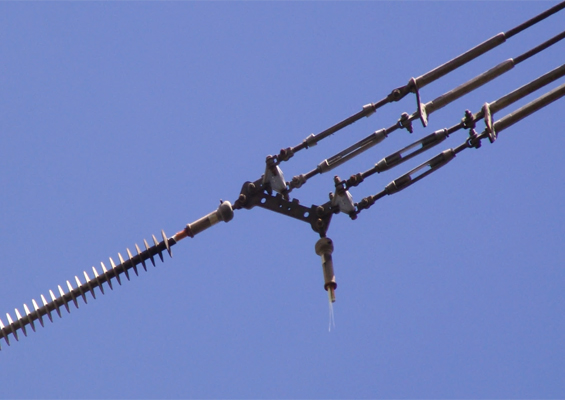
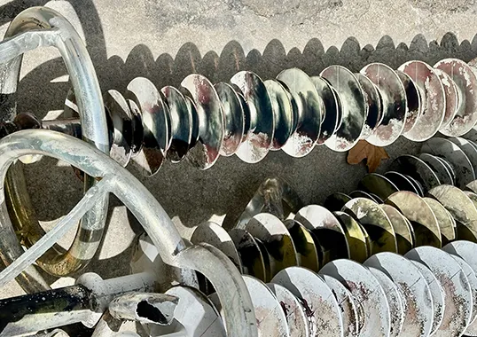
Several American utilities have already identified punctured units near the line end on long insulator strings (i.e. 230 kV and above). Mechanical failure of the string can occur during flashover when the arc transfers internally in such faulty units, thereby creating enough mechanical force to separate the porcelain from the hardware (as shown in Fig. 1). A proper understanding of the mechanisms responsible for such puncture problems can help manufacturers develop higher quality insulators. Similarly, utilities can use such information to eliminate inferior products from their networks.

Insulators Evaluated
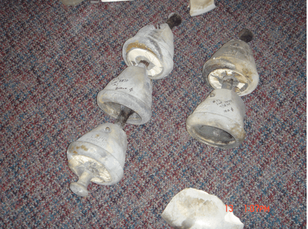
Suspension and dead-end strings that had been in service for 25-30 years were removed during regular maintenance. These insulators, it turned out, were supplied by five different manufacturers. They were standard profiles and the combined M&E (mechanical and electrical) ratings ranged from 67-178 kN (i.e. 15,000-40,000 lbs). These strings had caused several flashovers, and in one case, a line drop due to the porcelain being severed from the hardware. Apparently, there was no specific lightning, switching or bird related activity that could be associated with the flashover. Contamination was also ruled out as a cause owing to the relatively clean locations. Mechanical (tensile failure load) and electrical (puncture test in oil) were performed on all these units. Several units of porcelain from two of the manufacturers were punctured while there were no punctured units from the other three suppliers.
Results & Discussion
A. Scanning Electron Microscopy
The test specimens were obtained by chipping off porcelain from the skirts. Several samples were taken from insulators made by the different manufacturers. They were then coated with a 12 nm gold layer using a sputter coater. Figure 2 shows the typical microstructure of the different porcelain materials obtained under the same experimental conditions of accelerating voltage and magnification. The presence of pores can be clearly seen.
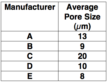
The dimension of the pores was taken in two perpendicular directions. Thirty pores were measured from each sample and the average of these measurements was used as a representative pore size for each sample (shown in Table 1). It is interesting to note that the microstructure did not reveal much difference in the pore size. However, there was considerable difference in the electrical and mechanical strengths of the insulators. This suggests that the other details such as quartz/alumina/mullite/corundum content, cement composition, porcelain-cement interface, assembly and manufacturing details play an important role in determining insulator performance.
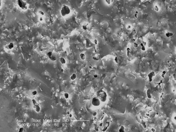
Accelerating voltage: 30 kV, magnification: 650X.

Possible Failure Mechanisms
Thermally Induced Failure
Heat generation and its subsequent accumulation within ceramic bodies is responsible for increased dielectric losses and can cause failure. Physical characteristics such as specific heat, thermal conductivity and coefficient of thermal expansion of the ceramic material are important factors influencing the destructive effects of heating. The specific heat value determines the temperature rise within a ceramic body for a given thermal conductivity and heat input. However, these values vary only over a relatively narrow range for most ceramic bodies.
In insulators, any condition favoring localized current flow increases the temperature of the ceramic with a cyclic increase in the localized body temperature resulting in establishment of high thermal gradients. Unequal temperature rise in a ceramic body is accelerated by non-uniformities at the microscopic level and due to lattice imperfections. Porosity also plays an important role in determining the thermal conductivity of a ceramic body. The thermal conductivity of wet process porcelain decreases with increasing porosity. The failure process can be aided by the presence of such localized high temperature regions within porcelain. They also accompany increased dielectric loss, decreased dielectric strength of the material and unequal expansion within the body that causes development of internal tensile stresses.
To understand the failure process, it is also essential to acknowledge the temperature effect on the dielectric constant of porcelain. The dielectric constant of most ceramic bodies increases with an increase in the temperature. As the temperature rises, the ionization and electric discharge process in pores also increase due to the presence of higher electric fields as an effect of this increased dielectric constant of ceramic material. As with most insulating materials, the dielectric strength of porcelain reduces with increasing temperature. Porcelain, like other ceramic materials, exhibits constant breakdown strength until a critical value of temperature is reached. Breakdown strength falls drastically at temperatures higher than this. This critical value of temperature is a material characteristic and varies from one ceramic to another. For electrical grade porcelain, this temperature is estimated to be about 100o C.

Effect of Pores on Mechanical Strength
The mechanical fracture strength of porcelain is inversely proportional to pore size. The smaller the pores, crystals and residual particles, the higher the intrinsic strength of the porcelain body. The strength of a material is dependent upon inter-atomic forces. The theoretical strength of a material is estimated to be approximately one tenth of the elastic modulus of the material. However, imperfections at the microscopic level can cause the experimental strength value to be much lower than the theoretical value. This reduction of mechanical strength is attributed to the phenomena of stress amplification in the areas surrounding the flaw. The magnitude of this rise is mainly dependent on orientation and geometry of the flaw.
Insulators in service always operate under mechanical stress while supporting electrical conductors. As a result, mechanical stress intensification as explained above accelerates the failure process.
Edge Breakdown & Treeing
The presence of pores causes electric field enhancement within the pore. At the cement-porcelain interface, one can expect heterogeneities, simply due to the multiple materials, each of which contain grains of different sizes. There is a bituminous coating that is applied on the inside of the metal hardware and this works like a stress-reliever. At the microscopic level, the various interfaces create numerous sites for electric stress concentration. The electric stress is higher in the void than in the surrounding porcelain by a magnitude that is equal to the dielectric constant of porcelain. Consequently, the gaseous part breaks down at relatively smaller stresses.
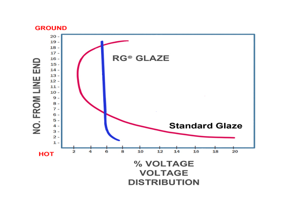
It has been reported in the literature that the dielectric strength of porcelain is about 14 kVrms/mm. Normally, each unit of an insulator string is subjected to about 10 kVrms. Units near the line end are subjected to a greater voltage especially on long strings (230 KV and higher) due to the non-uniformity in voltage distribution.
Under lightning and switching operations and also in long strings, the line end units can be subjected to several times this nominal value of 10 kV. This gives rise to localized electric stress in the 15 kV/mm value range, which is sufficient to initiate localized breakdown. With each surge, the breakdown channel will elongate. A complete breakdown may occur with formation of many such breakdown channels in the solid dielectric. Such a breakdown path assumes a tree-like structure due to its stepwise progression through the insulating media.
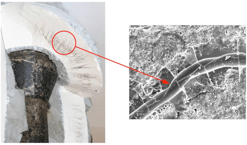
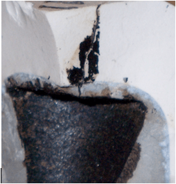
Fig. 3 shows two porcelain insulators that have been cut in the head region and having two different puncture patterns. Fig. 3a shows distinct channels in the form of a tree and straight channels which were examined in detail under a scanning electron microscope. A magnified image of one of the channels is also shown in Fig. 3a. It is interesting to note the phase change in the porcelain structure in the immediate vicinity of the channel. This region displays a glassy amorphous structure as opposed to the distinct crystalline regions further away from the channel. High temperatures (above 1300°C) must have been created locally to melt the porcelain and create this glassy appearance. Fig. 3b is a puncture that originated from the cement-porcelain interface. It appears that the bituminous layer has invaded the cement and subsequently created its own conduction path in the porcelain.

Electric Field Computation
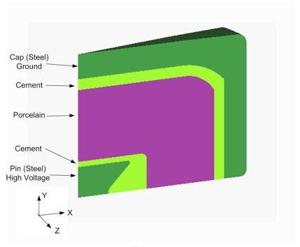
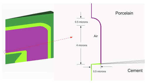
The electric field was computed using the 3 Dimensional Software Package Coulomb®. A 3-D scale model of the insulator was created as shown in Fig. 4. A hairline crack was modeled as a cylinder of diameter 1 µm and a height of 4 µm. The tip of the crack was simulated by a hemisphere of diameter 1 µm, as shown in Fig. 5.
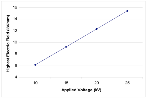
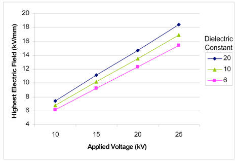
High voltage applied to the pin was varied to simulate unusual circuit conditions of faults and electrical transients. The highest electric field at the tip of the channel was computed for different voltages in the range of 10-25 kV applied between the cap and pin electrodes. The results are shown in the Fig. 6.
To capture the effect of increased dielectric constant, simulations were run with dielectric constants of value 6 (corresponding to room temperature) to a value of 20 (corresponding to a localized temperature of 400°C). It was noticed that with increasing dielectric constant, the highest electric field in porcelain also increases, further increasing the possibility of electrical breakdown.
Such high electric fields are sufficient to initiate breakdown inside pores and voids leading to electrical discharges. These repetitive electrical discharges over an extended period of time may cause enough breakdowns to form a tree-like between the electrodes and causing permanent failure.
Conclusions
Porcelain insulators can develop internal conduction paths during service and which will eventually cause puncture of the unit. The development of such channels is dependent on the materials, microstructure and interface details. It has been observed that there are porcelain insulators that did not display any internal degradation even though they were in service for the same time as the failed units. This demonstrates that the quality of porcelain insulators can vary widely among different manufacturers.
The electric field computations performed confirm the availability of localized high electrical stresses, especially during surges and for units near the line end of long insulator strings. This is shown to initiate localized degradation of material over a prolonged period of time. A tree-like structure of puncture paths confirms a slow degradation mechanism. Scanning electron microscopy demonstrates the existence of high temperatures at the tip of the channels.