Given the evolution in computing power and specialized software, finite element analysis (FEA) has evolved from what used to be a mainly academic pursuit into a much-used tool for product development. Engineering simulation technology, for example, allows detailed analysis of different configurations of complex power sub-systems operating across many different service condition scenarios. Hardware and software development have also improved design speed using FEA, allowing it to better align with manufacturing lead times. In this way, FEA has become valuable not only in verifying final design but also in designing power equipment as well as related insulation systems. Digital prototyping also allows engineers to quickly assess more design options and explore these alternatives thereby facilitating more innovative solutions. While FEA does not eliminate the need for physical prototypes, (these are still necessary to confirm whether or not physical and virtual reality line up), the process is considerably shortened since only one prototype has to be built and tested before entering production. Another advantage is that an FEA digital prototype, once validated, can be used to predict behavior of equipment by simulating different boundaries as well as load conditions faced under real service conditions – something that’s difficult to accomplish through type testing alone.

CLICK TO ENLARGE
An important factor in ensuring correct digital simulation is assessing the characteristics of each material that makes up the equipment and its insulating system as a function of all influencing parameters. For example, in the case of apparatus for DC applications, the resistivity of the single insulating material (which can vary from 1010 Ωm to 1018 Ωm) must be carefully determined, all the while considering its dependence on temperature. Moreover, in the case of introduction of new materials or components, mechanical properties such as modulus of elasticity or Poisson ratio have to be properly determined. This can prove highly complex for composite materials since various failure modes as well as strength in different component directions all have to be taken into account. In this regard, experimental characterization of a composite material is not easy and will probably require a great deal of testing.
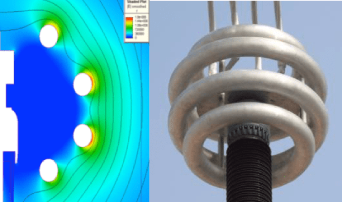
Correct digital representation of the physical model is also important. This must aim to simulate the model in all respects and with meshing sufficient to allow sufficient accuracy in the evaluation – all the while accounting for any limitations in computing facilities or software.
CLICK TO ENLARGE
Digital modeling by FEA must also take into account any physical constraints that might impact equipment reliability, such as electrical, thermal or mechanical variables – typically some interaction of the three. It is therefore necessary to carefully consider boundaries between systems and sub-systems within all the engineering constraints associated with these parameters. Ultimately, using FEA to verify the digital prototype from an electrical standpoint is essential to ensure that electrical stress is less than the strength of each material in any part of the equipment. In the case of electrical design of a bushing for DC application, for example, as stated above dependence of material resistivity on temperature must be considered. As such, preliminary thermal modeling of the bushing has to be conducted and, if necessary, interaction between electrical and thermal transients studied to verify that critical conditions are not reached in any portion of the bushing during such events.
Once the digital prototype has been defined from the electrical point of view, a thermal FEA can predict local hot spots. Since ohmic losses are related to resistivity of the materials and change with temperature, a preliminary thermal analysis can help adjust these values. Special attention in the digital prototyping must be paid to design of the cooling system by combining thermal and fluid-dynamic modeling (e.g. for bushings) since cooling design can drive choice of materials as well as mechanical solutions. Last but not least, the digital prototype has to be verified from a mechanical point of view, again using FEA. To run a reliable numerical analysis, the first step is proper schematization of the physical model, extrapolated from real life and taking into account any electrical or thermal constraints from previous studies. In addition to definition of geometry, preliminary steps have to include analysis of loads (depending on structural and application conditions) including: service stresses, transport stresses, earthquake and ice loads as well as any possible combinations of these.
Given the above, it has become apparent that systematic application of FEA is an essential tool not only to optimize design but also to reduce development costs. In particular, extensive use of digital modeling becomes a must in the case of UHV insulation systems, given the cost of physical prototypes that could extend up to 20m or more as well as the expense and complexity of related testing.
Contributed by Alberto Pigini (2013)

