Ensuring a high level of availability in supply of electrical power has historically been accomplished through sufficient system redundancy as well as specification of only well-proven and sometimes over-dimensioned network components. Intensive manpower and time-based maintenance schemes with relatively short inspection intervals have also meant that potential problems were usually discovered before failures occurred. However, deregulation of the electricity market has changed all this by placing much greater emphasis on purely economic considerations. As a result, time horizons for decisions about equipment replacement have generally been extended. Similarly, the drive to re-invest in and maintain the network has also typically been reduced. Taken together with increased and more dynamic loading, these changes have resulted in reduced safety margins. In order to maintain high levels of availability while also controlling maintenance costs in this new industry environment, power utilities must rely on tools that allow effective, and ideally automated, condition monitoring of equipment and components. Based on data obtained, actions such as maintenance, repair or replacement can then be scheduled in a timely manner. This type of information can also help optimize use of equipment, e.g. as in dynamic rating. This edited past contribution to INMR by Andreas Dernfalk, a Swedish-based expert in maintenance and diagnostics, examined technologies and tools available for improved condition monitoring.
Condition monitoring of network assets refers to the regular recording of operating parameters such as temperature, pressure, mechanical loading, leakage current, dielectric loss, gas concentration, etc. The next step, known as condition assessment or diagnostics, involves processing and interpreting all this data. Ideally, condition assessment should be based on data that most directly represents the property of interest, e.g. what is the residual lifetime or risk of failure of the component being monitored? Unfortunately, there are no parameters that will always yield a clear and unambiguous answer to this question. Instead measurements are limited to properties that only provide an indication of the condition of the equipment being monitored. Moreover, the parameters of primary interest can themselves not always be easily measured, due to practical limitations. This only further restricts the ability to draw firm conclusions.
In addition to the above general considerations, there are also several other requirements that should apply to any useful monitoring system:
• Continuous and reliable operation
• Robust evaluation method providing reliable results
• Environmentally friendly
• Exchangeable software and hardware
• Robust sensors
• Allowing for easy integration of existing monitoring systems
The following are four broad approaches to meet these requirements without necessarily focusing on any specific component or technique. These include: temperature monitoring, aided visual inspection, measurements of insulator pollution performance and methods for detecting cracks in energized porcelain insulators. Examples are also given of techniques for monitoring and diagnostics of certain overhead line and substation equipment.
Monitoring Temperature
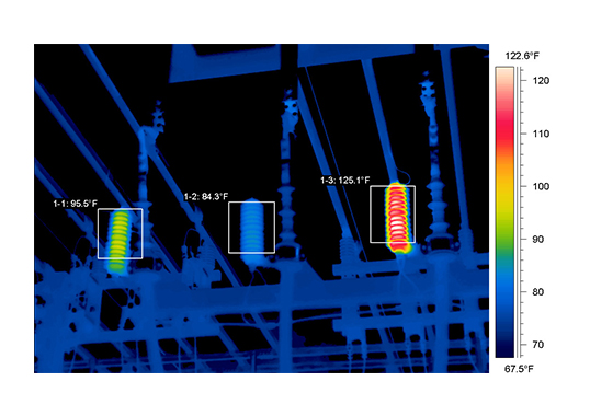
Monitoring temperature is already widely applied to characterize and identify problems in many industrial processes, e.g. energy conversion in nuclear power plants. In the case of condition assessment of electrical equipment, infrared (IR) inspection is also frequently used since it allows contact free measurements – a feature that is especially attractive in most HV applications. The capability to directly visualize results and quickly scan a large number of components makes the technique that much more valuable.
CLICK TO ENLARGE
Typical applications are periodic inspection in:
1. Substations, comprising checks of conductor clamps, disconnectors, bushings, transformers, arresters, etc
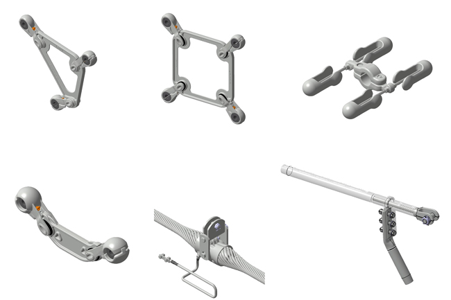
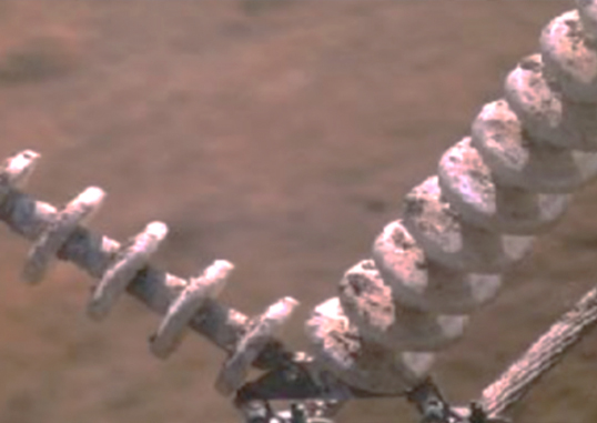
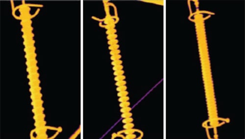
2. Overhead lines (OHL), where the main focus is generally on conductor joints and also on composite insulators (see Fig. 1). In the latter application, the infrared camera is often mounted on a helicopter to allow for a clear, unobstructed view as well as rapid transfer between inspection sites.
CLICK TO ENLARGE
CLICK TO ENLARGE
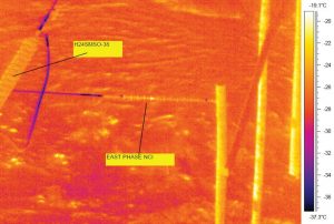
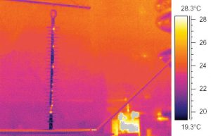
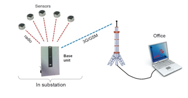
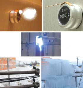
However, this approach suffers from several drawbacks. For example, in the majority of applications, the principle of such measurements is to identify a temperature increase that might be an indicator of a change in resistance due to ageing. Therefore, it is important that the current at time of inspection is sufficiently high to cause significant temperature rise. However, IR inspection is typically done on regular basis, usually once a year, without correlation to current loading. As such, temperatures recorded only reflect the condition at any single point in time. Moreover, weather conditions at the time of inspection can influence results and limit the value of comparing data from previous inspections. Unless suitable precautions are taken, these drawbacks can severely limit diagnosis of the real condition of components being monitored. Since optimal current and weather conditions for IR measurements are not usually known in advance of scheduled maintenance inspections, continuous monitoring of temperature offers a significant improvement. Installing IR cameras for monitoring purposes, however, is not considered cost effective. Instead, monitoring can be done in a better way by using special sensors that record temperatures at specific points of interest. One example of such a solution for monitoring temperature involved high voltage disconnector switches and was developed on behalf of the operator of the Swedish National Grid. The special interest in disconnectors in this case related to a past failure of such equipment, accompanied by overheating, that triggered events that resulted in a major blackout. In principle, the system developed for this application consisted of a number of small sensors that wirelessly communicate temperature readings to a base station, with results then made available to maintenance personnel via a web interface (see Fig. 2).
CLICK TO ENLARGE
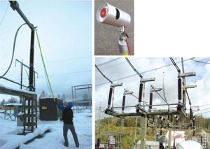
The concept here was to develop a small but robust sensor that could be used to continuously record the temperature of any disconnector contacts classified as ‘suspicious’ during conventional IR inspections. This way, they could be closely monitored until maintenance and/or replacement could be performed. However, as work on the project progressed, a wider application of this technology was foreseen, with monitoring of complete substations using a large number of sensors. The sensor in question was designed to operate under all the stresses typical of an outdoor substation environment. Before being tested in the field, performance was verified during a series of laboratory tests. Furthermore, one of the key requirements during product development was that the design should allow for easy installation on energized equipment using a hot stick – a feature that has since proven very useful.
CLICK TO ENLARGE
Since the sensors are battery-powered, temperature readings are not transferred continuously. Rather, desired sampling rate is set by maintenance staff utilizing the web interface. For example, based on a 10-minute sampling interval, the battery is designed to last a minimum of 5 years – considered sufficient in most applications. The design work for the sensor focused on reliability and robustness, which was then reflected in the physical design of the unit, while protocols for data transfer ensured correct readings. Furthermore, the modular design allowed for easy expansion of the system.
CLICK TO ENLARGE
CLICK TO ENLARGE
CLICK TO ENLARGE

CLICK TO ENLARGE
Visual Inspection
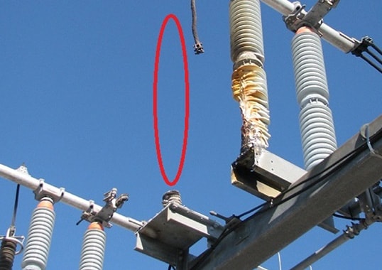
Visual inspection is the most frequently applied method for condition assessment of almost all equipment since it allows quick contact-free scanning. Shattered glass insulators, broken conductor strands, corrosion on towers, oil leaks, etc. can all be identified directly by the unaided eye (even though inspection quality binoculars clearly assist the process). Periodic visual inspection of OHLs is often performed from helicopter while substations are typically inspected from the ground. In both cases, the requirement for documenting observations make the use of cameras a natural complement to written notes. Photographs of failed or suspicious components also help maintenance staff identify the appropriate type of corrective measures needed.
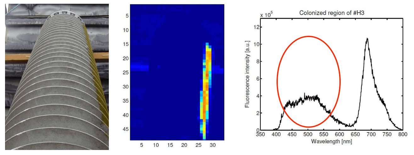
To better assist such inspections, information about the condition of components comes not only from the visual wavelengths but also from the IR and UV bands of light. This requires utilization of special dedicated cameras that present radiation in these ranges as color-coded images. As already discussed, IR emissions suggest heat and are therefore used for temperature measurements while the shorter UV wavelengths can be used to detect the presence of corona and discharge activity. Applications for such imaging cover a wide range, from verifying the correct installation of field grading rings to inspecting cement inside the cap of porcelain disc insulators. Apart from the requirement of a good view of what is being monitored as well as suitable climatic conditions, correctly interpreting what is being observed usually requires skilled operators. The above techniques, however, while useful, are essentially passive in that recorded light is either reflected from the ambient (i.e. sun) or generated by the object being studied. Expanded information on the condition of whatever is being inspected can be achieved by exciting its surface using a laser beam of selected wavelength and then recording the test object’s response in the form of emitted light. This approach, for example, has been applied in experiments on composite insulators where the presence of biological growths such as algae could be detected from a distance of as much as 60 m (see Fig. 8). While such methods are still not fully ready to be applied for inspection purposes, applications are expected to arise in the future as this technology is perfected and made more user friendly.
CLICK TO ENLARGE
Visual inspection performed with or without these types of imaging tools has primarily been applied for periodic manned inspection of different components in the network. By contrast, continuous monitoring is typically preferred to assure greater substation security as well as safety of personnel. Application of permanently installed cameras (operating in the visual, IR or UV range) dedicated only to monitoring substation equipment is still rather limited. One reason for this has been the difficulty in automatically interpreting the images being recorded. However, rapid developments in computer and software engineering are now allowing advanced analyses to be rapidly performed, similar to what is being achieved in face recognition.
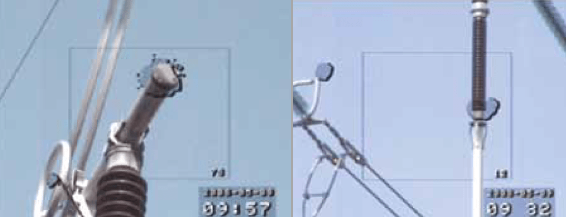
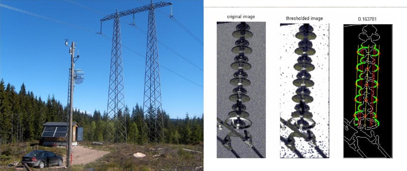
An interesting example of what can be achieved in this area is a system developed on behalf of the TSO in Norway intended to monitor insulators with respect to snow and ice performance. Using permanently installed cameras as well as an adjacent weather station, snow and ice accretion on different insulator types/profiles are evaluated in the field under varying conditions (see Fig. 9). Special software automatically identifies snow coverage as well as insulator swing angles while weather data is transmitted along with information from the images via a web-interface. A methodology that provides an estimation of the visual impact of the insulators under study is also being implemented. The aim here is to evaluate different types of camouflage to make insulators less visible under typical Norwegian conditions.
CLICK TO ENLARGE
It may not seem reasonable to believe that static cameras will be suitable for automatic condition assessment of substation equipment in the near future. Still, specialized such mobile units with interpretation support software might well soon be available for periodic inspection or monitoring of equipment of special interest.
Verifying Pollution Performance
Pollution performance is often the determinant factor in selecting and dimensioning insulators when designing a new OHL or substation. In this regard, insulators are chosen based on information regarding insulation strength (with respect to pollution) and also environmental characteristics, often applying statistical methods. The data required on insulation strength can then be obtained either from laboratory tests or field experience. Environmental data typically relies on observations or estimations of service conditions at the site of interest. One methodology to assess the environmental stress at a specific site and verify actual pollution performance is to use a leakage current monitor installed on a nearby existing line and combine the data recorded with information from a weather station. This approach has been applied at two sites in Scandinavia – one for an AC overhead line and the other for a DC overhead line. The system collects data via GPRS-modems in the instruments at site and allows convenient access to recorded data via a web-platform.
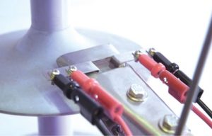
For insulators made from hydrophobic transfer materials (HTM), the continual ability to transfer hydrophobicity to the surface pollution layer is crucial to performance. In the laboratory, this can be studied through measurement of contact angles. In the field, however, investigations are often limited to assessment of wettability class or measurements of surface resistance. In order to best describe to what extent the housing material of an insulator is able to transfer its hydrophobic properties to the pollution layer, a parameter referred to as hydrophobicity transfer (HT) has recently been proposed as follows: HT= (ESDD-ASDD)/ESDD. In this equation, ESDD refers to the standard IEC 60815 parameter and ASDD is the Apparent Salt Deposit Density. Standard ESDD measurements require that all salts from the surface are dissolved, which obviously results in an over-estimated value in the case of HTM materials. ASDD is therefore measured only when the non-embedded salts are dissolved. An HT value of 1 therefore means that there is an efficient, perfect transfer of hydrophobicity through the pollution layer. In practice, measurements are performed using a conductivity cell placed in contact with the insulator’s surface (see Fig. 10), which then constitutes the bottom of the cell filled with a known volume of distilled water. The stable current resulting from application of a voltage between electrodes for approximately 30 min is then used to calculate ASDD. The insulator surface is later scratched by a spatula, which serves to bring most of the encapsulated salt into solution. The resulting stable current is used to calculate ESDD. So far, this methodology has been applied mainly for laboratory evaluation of insulators removed from service. However, to extend it for field-based evaluation as part of an inspection process would be straightforward.
CLICK TO ENLARGE
Detecting Cracks in Porcelain
If there is not a continuous high quality control during the porcelain manufacturing process, there is a risk of defects that will eventually develop into cracks and diminish mechanical performance. This is especially dangerous for humid service environments where temperatures can fall to close to zero. Indeed, the risk that a porcelain insulator might break mechanically is of great concern to power utilities since this could lead to a permanent fault condition and endanger safety. At present, there are basically four approaches available to detect potentially dangerous cracks in porcelain insulators:
1. visual inspection (for external cracks only),
2. ultrasonic inspection
3. acoustic emission measurements under mechanical stress
4. vibro-acoustic response measurements.
CLICK TO ENLARGE
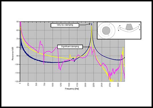
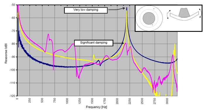
The latter two techniques have been developed and have been applied in Russia – a country that has traditionally been strong in detecting defects in porcelain insulators. Unfortunately, most instruments that are now used to detect cracks in porcelain require direct access to the insulator. The possibility to perform live-line inspection is therefore limited. The alternative of utilizing sound to provide the required excitation energy as well as to transfer information regarding insulator response to the operator was therefore explored in a recently published feasibility study. Measurements were performed in the laboratory on both porcelain cap & pin and small support insulators using mechanical and acoustic excitation. Responses were then recorded using piezoelectric sensors and microphones (see Fig. 11). Based on results, it was concluded that acoustic/vibration measurements could indeed be applied to detect cracks in porcelain. However, one of the challenges associated with performing such measurements in the field is to achieve sufficient spatial resolution and power density, especially if the test object is relatively far away. Nevertheless, this inspection technology is seen as attractive since it will allow for truly remote measurements.
Summary
Condition monitoring and diagnostics of network assets have become increasingly important to power supply utilities in order for them to be able to maintain high system reliability and availability while at the same time keep maintenance costs to a minimum. As discussed, existing approaches are continually being improved while entirely new techniques are coming on stream due to new technological developments. Wireless monitoring solutions, such as the temperature sensor described above and which is made possible by advances in radio and battery technologies, is but one example. The application of these types of distributed, self-contained sensors that provide readings of several different parameters to diagnose or assess the condition of equipment will become increasingly attractive.

