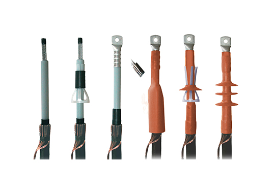
Among the different possible constructions, slip-on technology has grown to become the world standard to connect extruded high voltage cables. One of the reasons for this is that use of pre-fabricated, routine-tested components for the main insulation minimizes risk of faults during installation. At the same time, demand for higher voltage levels, combined with advances in XLPE materials, is resulting in cable designs with higher field stresses placed on their accessories. To allow progress to continue, there will be a need to optimize electrical design and further improve both material and production technologies.
Mechanical properties of cable systems will also need on-going development. With many installations now taking place under demanding site and service conditions, robust and suitable designs will be required to ensure trouble-free service. Moreover, since the quality of an installation can differ from one country to the next, a certain fault tolerance will be yet another characteristic needed in the next generation of accessories.
Apart from the expertise required to design cable accessories for high and extra high voltages, suppliers in this business must also maintain large investments in production and testing facilities. Moreover, since pre-fabricated insulating parts are only suitable for a defined range of cable dimensions, different sizes have to be offered depending on voltage and cable cross-section. That means additional investment, this time in moulds for each size. Ideally, some standardization will be desirable to limit the number of possible different parts.
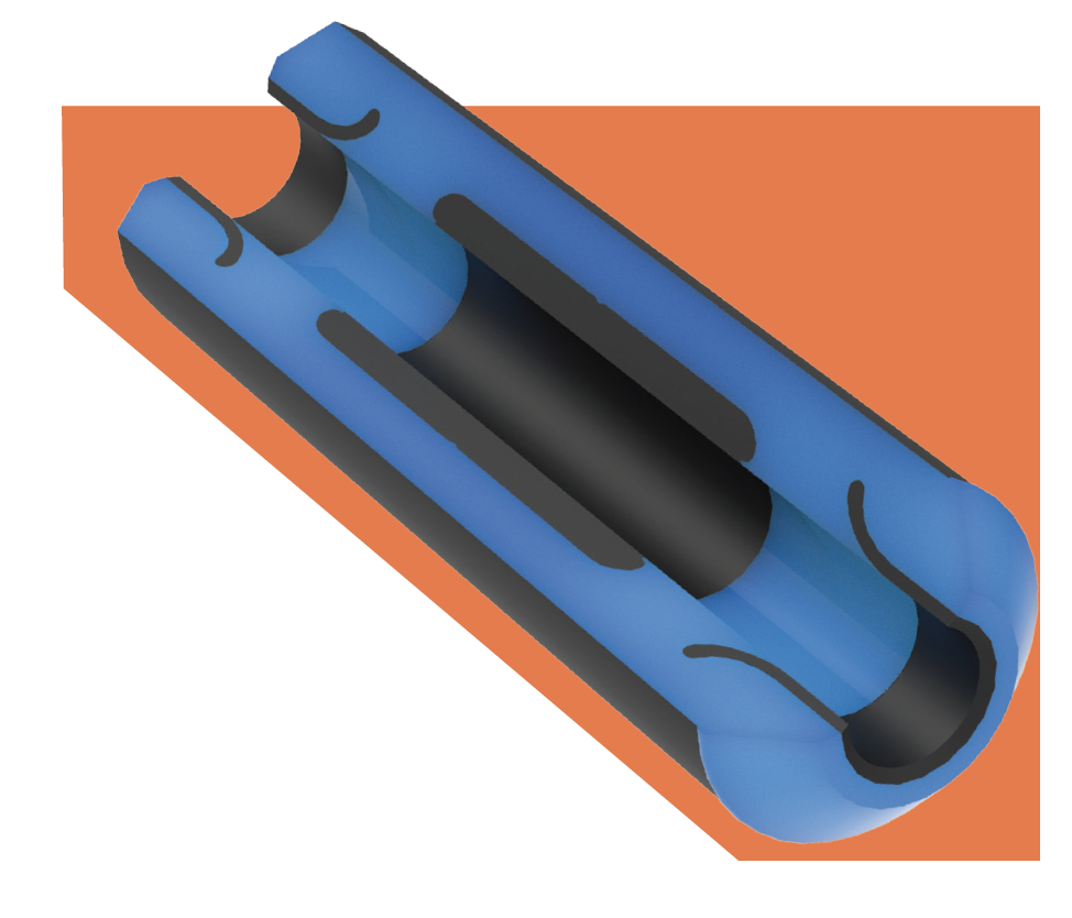
Modular layouts for rubber components can help in this regard by allowing more cost effective production as well as stock keeping. Moreover, since changes in design are costly, it will also be important to develop layouts that can be used on all the different types of construction offered by manufacturers of cables.
Finally, international standards for cables and their accessories require factory-tested components. In this regard, routine testing is an additional cost driver in this business. While opportunities to optimize already well-defined test procedures may be limited, more sophisticated equipment and handling of samples could still help reduce testing costs.
This article from 2017, contributed by Thomas Klein, Eckhard Wendt and Stefan Zierhut of STRESCON – a German firm of experts, specializing in consulting on cable ac-cessories – reviewed these challenges and proposed recommendations to deal with them.
The cost effectiveness and reliability of insulating components used in accessories such as stress cones and joint bodies depend greatly on the sophistication of the layout where they are produced. Fortunately, the insulation of modern XLPE cables is now more or less standardized and that means there is no longer a need to customize stress cones in each case. Indeed, modern accessories can meet the requirements of all XLPE cables being supplied by different manufacturers. However, international standards still ask for a common type test to guarantee this – a reasonable requirement given that there can be significant differences in insulation dimensions when it comes to HV cables.
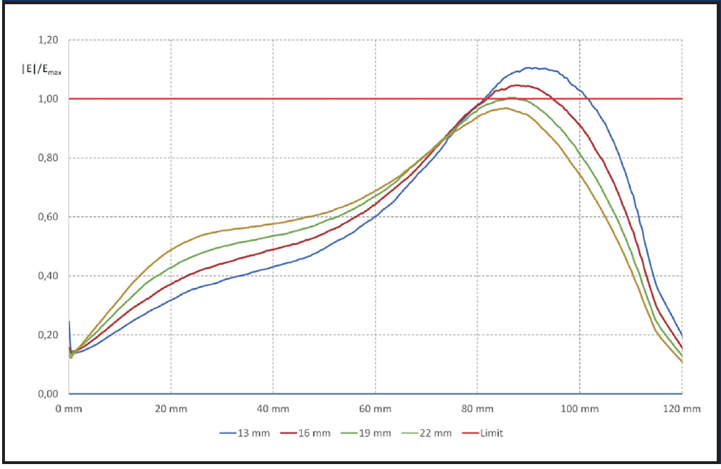
For example, 245 kV cables from some manufacturers have insulation thickness of 22 mm or more while this is only 16 mm in the case of other suppliers. Combined with allowed tolerances, eccentricities and further reduction in thickness by peeling during installation, accessories may have to manage the enhanced field stress of only 13 mm of XLPE insulation. Fig. 1 illustrates the tangential component of field strength along the interface between cable insulation and an accessory’s stress cone rubber. It is apparent that the accessory could not be installed on XLPE cables with insulation thickness below 19 mm.
CLICK TO ENLARGE
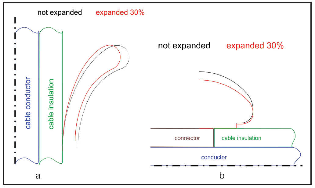
However, given optimized layout of stress cones and deflectors (i.e. the embedded semi-conductive elements), maximum field stresses can be reduced and make these products suitable even for thinner cable insulation. Such an optimization process can be achieved using numeric simulation tools. In this regard, it is essential to also include the deformation of the expanded stress cone or joint body after the process of slipping it onto a cable – an effect that is especially relevant when simulating joints and fluid-filled terminations. This is because, for these types of accessories, there are no additional mechanical forces available apart from expansion to create defined pressure between cable insulation and stress cone or joint body. Such pressure is needed to ensure sufficient electrical strength along the interface, given high tangential stress. All cable accessories of this type use geometric-capacitive field control, which is highly dependent on shape of the integrated conductive parts, i.e. the deflectors. Fig. 2 demonstrates deformation caused by expansion.
All cable accessories of this type use geometric-capacitive field control, which is highly dependent on shape of the integrated conductive parts, i.e. the deflectors. Fig. 2 demonstrates deformation caused by expansion.
CLICK TO ENLARGE
Deformations of deflectors and stress cones can cause increased field stresses in the accessory. Because of the wide range of possible cable diameters, a certain accessory design calls for a number of stress cone sizes. To keep this number as small as possible requires optimized deflector designs. It is also important to take into account both minimum and maximum expansion for any given size of stress cone or joint body. The objective in both cases is that all parts remain within the safe limits of electrical stress for that given design. The best field distribution will be reached at some intermediate expansion. Only in very specific cases will deformation phenomena limit the expansion range of field control elements. Usually, the minimum expansion is given by the required pressure, while the maximum by the mechanical properties of the elastomeric material such that no ripping occurs due to overstretching.
But reliability is not the only important characteristic of cable accessories these days. With the huge diversity in cable dimensions (e.g. voltage levels up to 550 kV and conductor cross-sections up to 3000 mm2), many sizes of insulating components are needed. Since pre-moulded parts are involved, that translates into large investments in moulds for all the different types and sizes of insulating components. Cost efficient layouts are therefore essential and can be achieved by ‘modular designs’ of these parts, where this term means that identical insulating components can be used for different types of accessories, provided cable dimensions are the same. For example, the same earth deflectors can be used for stress cones of fluid-filled and dry-type terminations and for joint bodies as well. This helps reduce both mould and stock keeping costs.
Production Technologies
Silicone Rubber
These days, silicone rubber is used widely in MV and HV cable accessories as the key raw material for stress cones and joint bodies. The reason is its outstanding properties and also the wide range of available formulations. Together, these mean the possibility of customizing properties as well as relative ease in adapting production processes to meet the needs of different applications.
CLICK TO ENLARGE
CLICK TO ENLARGE
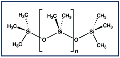
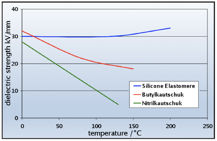
The main component in silicone rubber is polydimethylsiloxane (or PDMS) synthetic polymer. Its molecular structure sees the ‘backbone’ constructed from repetitive sequences of silicon (Si) and oxygen (O). Bonding strength between these elements has the relatively high energy of 451 kJ/mol versus 348 kJ/mol and 352 kJ/mol respectively in the C-C or C-O bonds found in organic polymers. This higher bonding energy results in thermal and UV stability as well as resistance to ageing. In addition, silicone rubbers are characterized by high flexibility over a broad range of temperatures, remaining flexible and showing elastic properties even down to -50°C. Another advantage is the low temperature dependence of their electrical properties, as illustrated in Fig. 4, which charts dielectric strength (DS) of different rubbers as a function of temperature. Over the temperature range studied, the DS for silicone rubber is nearly independent of temperature.
The desired life expectancy of stress cones and joint bodies for HV and EHV applications, under the usual electrical and mechanical stresses, is greater than 40 years. Silicone rubbers fulfil this requirement. In fact, the literature presents several cases of life curves of silicone HV and EHV cable accessories where measured and extrapolated withstand values demonstrated a service life of over 50 years under typical working conditions and at nominal field strength (E0).
CLICK TO ENLARGE
Due to its low viscosity and simple processing RTV-2 silicone rubber used to be the preferred insulation material for stress cones and joint bodies. These days, liquid silicone rubber (LSR) has become the material of choice due to the relative ease in adapting its formulation to match desired properties and also the benefits it offers during production.
Production Processes
Two significantly different silicone rubber materials are used for the components that make up stress cones and joint bodies. The earth deflector and HV electrode (examples in Fig. 2 show geometric field control) must be made from semi-conductive silicone rubber while the embedding body from insulating rubber. The interface between the two requires special attention during production and high adhesion must be achieved such that there is no risk of material fracture during interfacial testing. In this regard, a combination of semi-conductive and insulating LSRs is particularly suitable because adhesion can be achieved without a special adhesion-promoting agent.
Similarly, as nominal voltage increases, the presence of dust and particularly conductive dust particles becomes more critical in the interface and in the insulating material because of increasing field strength in these areas. Production of HV and EHV insulation bodies must therefore be carried out under dust reduced or even clean room conditions and semi-conductive deflectors must always be carefully cleaned prior to use. The following parameters are crucial in influencing layout of the production process:
• mass/volume of articles;
• types of silicone rubber selected;
• forecast numbers of articles;
• numbers of variants.
In addition to design, selecting equipment such as metering and mixing machines, clamping units and injection moulding machines determines not only the design of moulds but also the production process. Important parameters here include:
• number of cavities;
• changeable inserts to cover variants;
• location & design of gate systems;
• design of de-airing;
• layout of material overflows;
• use of vacuum;
• layout of mould heating;
• de-moulding concept of vulcanized articles;
• surface properties inside the cavities.
An injection moulding process should be selected for producing HV stress cones with shot volumes below 10 litres. An LSR with good mechanical properties, high tensile strength and high tear strength is the best raw material. Generally, such types have comparatively high viscosity but this is not a problem when using an injection moulding machine, which also ensures stable conditions from one shot to the next. The following requirements must be fulfilled and indeed are typically met:
• production of some thousands of pieces/year;
• flexible but also economic production of small to large lot sizes;
• coverage of all variants;
• minimal number of tools;
• largely rework-free components & stress cones;
• no use of adhesion promoters;
• semi-automatic manufacturing processes.
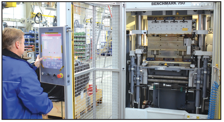
Moulds for conductive deflectors of stress cones are designed as four cavity tools. Interchangeable cavity-inserts allow flexible placement as needed. Also, stress cone moulds are designed as two cavity tools. The deflectors are inserted by hand. Dosing of the injection cylinder, injection into the moulds, temperature monitoring, vulcanization time and opening movements of the moulds with extensive de-moulding of the parts are all controlled by the injection moulding machine.
The operator only needs to remove completed stress cones from the mould, clean the cavities, insert new deflectors and re-start the semi-automated process. Use of multi-cavity tools results in shorter curing times per moulded part. As discussed, selecting different LSR materials ensures perfect adhesion of the insulating body onto the semi-conductive deflectors without need for an adhesion promoter. The overall result is an economical production process.
CLICK TO ENLARGE
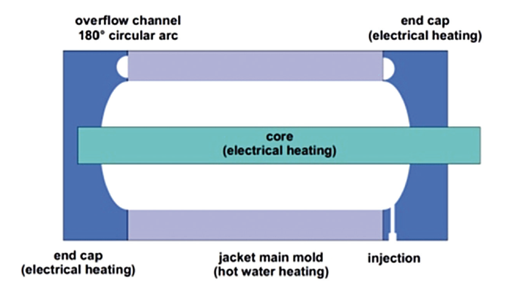
In the case of HV stress cones and joint bodies, volume of insulation becomes more important in determining optimal production process. Since volume of the insulation body grows considerably with increasing nominal voltage, vulcanization time also increases greatly. Based on experience, production of HV joint bodies with nominal voltage of 110 kV or Photo: courtesy of HIGHVOLT Prüftechnik.higher is no longer economical on a large injection moulding machine. Rather, for larger insulation bodies (i.e. volume > 10 litres), a different production process should be used. The design principle of a mould for HV joint bodies is shown in Fig. 5. The mould parting surfaces are located outside the electrically stressed areas of the joint body. Alignment of the mould can be horizontal or vertical during the filling operation and subsequent vulcanization. A tilted position of the mould, which allows for improved de-airing, is achieved during filling.
The mould is installed in a hydraulic clamping machine. This allows easy opening and closing of the mould for inserting deflectors and de-moulding of the finished joint bodies. Moreover, the clamping machine prevents risk that high internal pressures during vulcanization will open the mould. To fill the mould, a twin-type dosing and mixing machine is used so that constant supply of material is guaranteed.
A hot water heater is used for the main heating of the mould. By simultaneously also using a chiller, the mould can be heated or cooled rapidly. As such, a complex temperature profile can be run, if required, during mould filling and vulcanization. In spite of this, vulcanization times are still relatively long due to high insulation wall thicknesses. Shortening curing times can be achieved using a pre-heater (e.g. AVT). Here, the already mixed LSR is heated to an increased temperature of ΔT ~ 50K before entering the mould. A reduction in vulcanization time of from 30 to 50% can be achieved this way but it then also becomes necessary to select LSRtypes with sufficiently low viscosity to minimize pressure loss. This process for production of large-volume joint bodies can also be largely automated such that only minimum manual work is needed. However, operation of the more complex system requires trained staff.
Routine Testing
IEC 62067 and also other standards require carrying out a routine test on each length of cable as well as on the main insulation of all pre-fabricated accessories. This consists of an AC partial discharge test and an AC voltage test, ranging from 318 kV at 245 kV Um to e.g. 440 kV at 420 kV Um. Depending on rated voltage, such testing will take 30 or 60 minutes.
Voltage Source & Layout
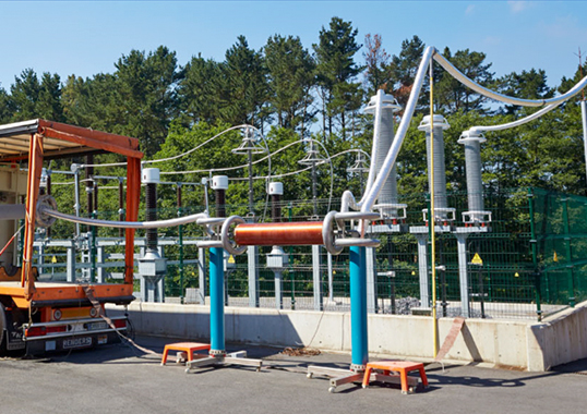
Based on available floor space, the voltage source can be designed as a normal oil-insulated transformer with a high voltage bushing for the secondary. An enclosed high voltage test bay is then used to contain the transformer and all the rest of the set-up. Connections of the components can be air-insulated but, considering the high test voltages for accessories of 245 kV Um and above, safety clearances become large and a considerable area is needed. In operation, strict access restrictions have to be applied. In addition, the test bay should be shielded for higher sensitivity in measuring partial discharges.
CLICK TO ENLARGE
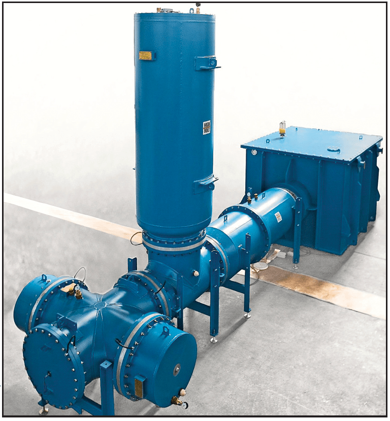
By contrast, using an SF6-insulated set-up allows for a more compact layout and the metallic shield of the GIS allows good performance in PD tests. All components are built into metallic enclosures, normally tubes made from aluminium alloy similar to the type used on grid-connected GIS.
Depending on number and duration of routine tests, a relatively inexpensive gas-insulated transformer can also be used. This design is similar to a large instrument transformer built inside an SF6-filled tank. The only disadvantage is ineffective cooling of the windings and core. Therefore, in the case of heavy usage, oil-insulated transformers with an oil-SF6 bushing are generally used.
Some tests specify an SF6-environment to control high electrical stress at a simulated accessory rig and this requirement obviously encourages using a GIS layout for the complete system. It is useful to have a number of separate test bays made from ‘empty’ sectors of GIS tubing with some kind of standardized connector to the high voltage conductor or fitted with a socket for high voltage cable connection with a GIS accessory. This bay can be separated from the voltage source using a single-pole busbar with disconnector and earthing switches. Expensive circuit breakers are therefore not needed. This way, it becomes possible to apply pressure or evacuate some test chambers while tests are underway in others.
Test bays are to be filled with SF6 or, in case of test voltages below ≈ 200 kV, with clean air at a pressure of 0.2 to 0.7 MPa. For SF6, the test bay has to be evacuated and the gas stored in a tank every time the bay needs to be accessed. Similarly, ambient air has to be evacuated before the compartment can be re-filled to avoid contaminating the gas. The SF6 service equipment utilized for this procedure becomes a critical factor determining cycle time of the whole test set-up and therefore it would be a false economy to skimp on this. Access to the test bays is by means of a pressure tight hatch or lid. The procedure to exchange test specimens in a bay is made even more efficient if these are fitted with hinges and fast opening toggle screws.
Test Set-up
As required in IEC 62067, the routine test can be done either by testing the ‘main insulation’ of pre-fabricated accessories installed on a piece of cable or by using a so called ‘host accessory’ or ‘simulated accessory rig’ for components of the accessories. The latter may necessitate use of voltage higher than normal test voltages to ensure that the electrical stresses in the accessory components are at least as high as in the complete accessory when subjected to test voltage. The most suitable way of installing the accessory’s main insulation parts or components for any test will depend on the kind of accessory and the design in question.
Joint Body
Joint bodies made from one single part generally test well on two pieces of cable. The outer semi-conductive layer contains the electric field inside of the joint body, permitting an easy test set-up in air under atmospheric pressure. It is common to temporarily apply an additional conductive outer layer and perhaps an insulation layer as well for protection. Owing to the design of the screen gap, this area has to be monitored separately. The joint body is installed on specially prepared cables whose diameter provides the minimum mechanical expansion needed to cope with the electrical stress along the cable-silicone interface. If expansion is too high, the mounting process becomes tedious and the joint body is unnecessarily pre-stressed mechanically.
However, the installed joint body tends to release part of the mechanical stress by pushing the two pieces of cable apart. Because of this, the cable has to be held in place inside the joint body either by some kind of special connector or by an external mechanism that ensures the correct position of the edges of the cable screens and of the connector inside the joint.
For accessories of considerable size, mounting can only be done by means of some mechanical or hydraulic apparatus. This equipment can also be used to keep the cable positioned correctly. A well-designed rig for this purpose can prove helpful to assure successful mounting and good test results each time.
Outdoor & GIS Terminations
In regard to GIS and normal outdoor terminations, the consensus is that the stress cone is the only part of the main insulation needing routine testing, aside from the GIS sockets. In the case of outdoor terminations, the stress cone will be installed on a piece of cable with appropriate diameter and set up in a GIS arrangement. The cable end would then be shielded by some kind of spherical electrode. Gas pressure is correct provided that the electrical stress in the stress cone is well within the limits of the design but still somewhat higher than would normally be the case in the complete outdoor termination. This fulfils the requirements of the standard.
Depending on design of the GIS termination and socket, this type of stress cone can normally be tested the same way. The sockets are also installed in a GIS compartment. In case of the GIS system being designed for higher operating voltage than the accessory under test, some kind of metallic tube or sleeve will often be needed inside the test chamber to adjust electrical stress on the test object

