Polymeric and ceramic insulators differ since the surface of the former is often made of a hydrophobicity transfer material (HTM). But hydrophobicity level can change over time depending on voltage and environmental stresses. That means pollution withstand can vary as well. As such, while both laboratory and field pollution withstand for porcelain and glass insulators are a function of only insulator set geometry, in the case of polymeric insulators this will also vary with surface condition. Moreover, while for ceramic insulators pollution withstand is the design value under polluted conditions, in the case of composite insulators ageing can occur at voltages significantly below withstand if leakage current is present – even if of low magnitude. Different design margins therefore have to be taken into account versus ceramic insulators. There have been many attempts to set up suitable pollution tests for composite insulators, including tests based on salt fog, with particular attention to the quick flashover method and solid layer tests where insulators are pre-conditioned with kaolin. The insulator is then contaminated with a slurry of kaolin and salt with different recovery times (as described in CIGRE TB 555). Similarly, there have been tests with solid layer pre-conditioning of insulators with kieselguhr followed by contamination with a slurry of kaolin, kieselguhr and salt so as to simulate wettability levels from 1 to 7. Such experience is presently available mainly for line insulators and for AC voltages. By contrast, experience with large diameter station insulators and also under DC is more limited even though these are the cases where design is determined largely by pollution.
In this edited past contribution to INMR, industry expert, Alberto Pigini, analyzed available test experience and indications for insulator design that derived from this.
Salt Fog Test Experience
Tests with Standardized Procedure
Extension of the standard procedure based on three ‘one hour’ withstand tests (as per IEC 60507 or 61245) to composite insulators is problematic. This is due to the fact that pollution performance depends on surface condition of the insulators and this will vary with degree of conditioning. For example, Fig. 1 reports results obtained under AC voltage on one insulator type by pre-treating the polymeric surface with a slurry of water and kaolin or with only with kaolin (clay). Different surface rubbing procedures were used with the goal of investigating insulator pollution performance in terms of unified specific creepage distance (USCD) versus surface wettability, W, the latter determined according to IEC-TS 62073. Dependence of pollution performance on surface hydrophobicity is evident. Consequently, adoption of the standardized procedure would need, a priori, to define the pre-conditioning methodology in order to obtain repeatable, reproducible as well as representative results.
Experience with Quick Flashover Method as Diagnostic Tool
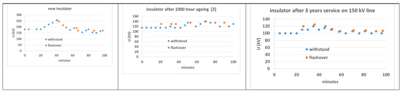
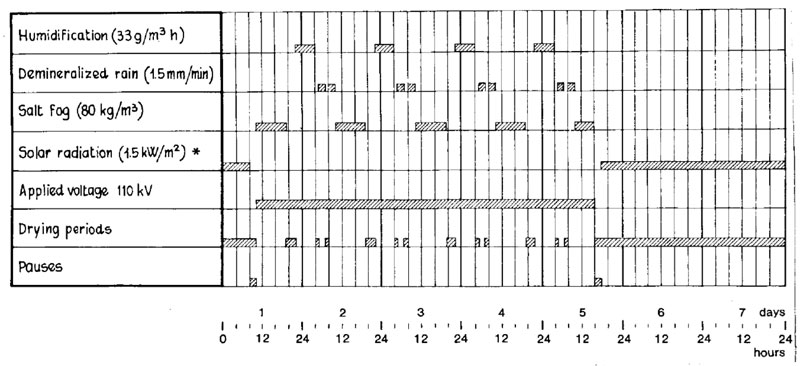
This method is performed using a variable voltage application procedure. Initially, a voltage lower than expected flashover voltage is applied and maintained for a period of 20 minutes. Then, voltage is raised in 5% steps until flashover, maintaining voltage for 5 minutes at each successive step or up to flashover. In the case of flashover, a voltage equal to 90% of the previous voltage is applied. Again, voltage is increased in steps of 5% until the next flashover. The test continues until a stable flashover voltage is obtained, i.e. the difference among the latest 5 flashover voltage values are lower than 5%. The average value of these last 5 flashovers is assumed to be an estimate of insulator performance. An example of such a procedure is shown in Fig. 2. Here, tests with AC voltage aimed to demonstrate the power of this methodology as a diagnostic tool to compare performance of new insulators, insulators aged in the laboratory and insulators after some years’ service in the field. Tests on the new (virgin) insulator highlight a high flashover value. In particular, the first flashover value is close to that obtained on an air gap distance equal to insulator arcing distance. Then, flashover voltage rapidly decreases due to the conditioning caused by the subsequent flashovers, reaching a stable value. The test was repeated after a 1000-hour artificial ageing test by submitting the insulators to the repeated weekly stress cycle shown schematically in Fig. 3. In this case, there is no significant decrease in flashover voltage with number of flashovers (i.e. the insulator appears conditioned by ageing). Moreover, the insulator shows a significant decrease in flashover voltage at stabilization with respect to the virgin insulator. A third insulator of the same type, sampled from a 150 kV line after three years of operation, was also tested with the quick flashover method. The results, reported in Fig. 2, are similar to those obtained on the insulator after 1000 hours laboratory ageing, indicating the power of the method as a diagnostic tool.
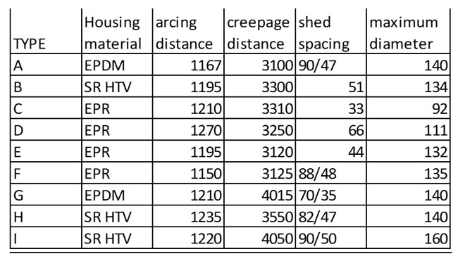
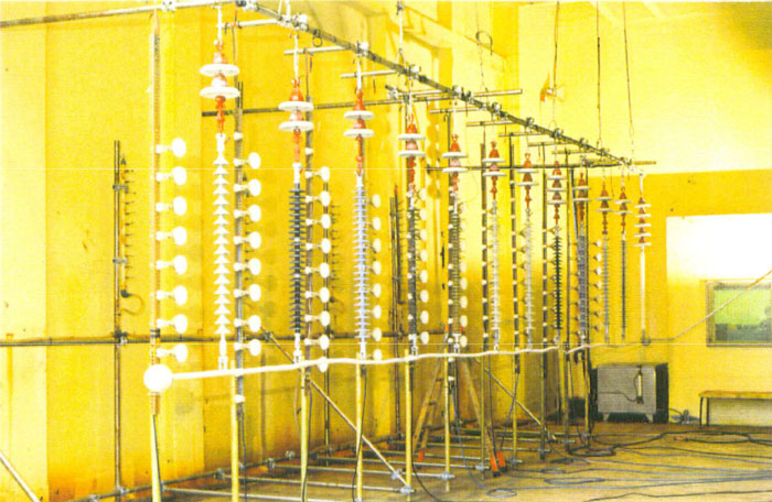
The quick flashover method was applied to evaluate insulators of different type and material (see Table 1). Insulators were characterized by different materials (EPR – ethylene propylene rubber; EPDM – ethylene propylene diene monomer rubber; and SR – silicone rubber) and different geometric characteristics. Quick flashover tests were performed before and after 3000-hour ageing tests carried out by repeating the weekly cycle in Fig. 3 (see test arrangement in Fig.4).
Comparison of the insulators in terms of unified specific creepage distance (USDC) required under DC voltage is shown in Fig. 5. In the extreme ageing conditions being simulated, EPDM and EPR insulator performance was found better than that of SR. This is probably because, in that condition, material resistance to tracking and erosion is more important than HTM characteristics. Quick flashover test results, together with all other evaluations reported (e.g. visual inspection of degradation, leakage current, etc.), were used to obtain an order of merit of different insulators and, again, as a diagnostic tool to obtain an indication of relative performance following the laboratory ageing test. Results of these tests at salinity of 80 kg/m3 are plotted in Fig. 5 in terms of USCD.
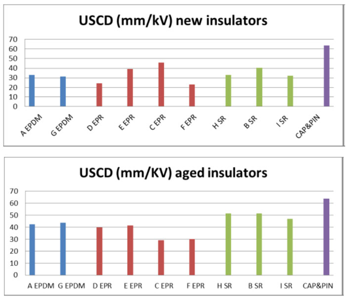
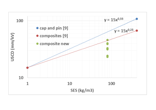
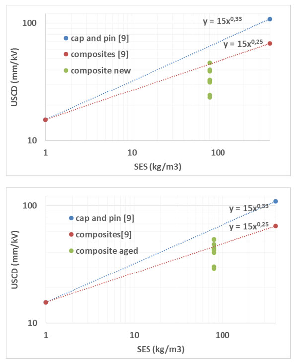
It is interesting to compare these USCD values with those of the USCD-SES model where SES (site equivalent salinity) is assumed equal to Sa. Such comparison is reported in Fig. 6 for both un-aged (top plot) and aged insulators after the 3000-hour test (bottom plot). The same figure also reports the USCD-SES model for ceramic cap & pin insulators. Comparison highlights that, while the un-aged insulators require lower USCD values than suggested by the USCD-SES model for composite insulators, insulators after the 3000-hour test need USCD values that are in good agreement with the indication of the USCD-SES model.
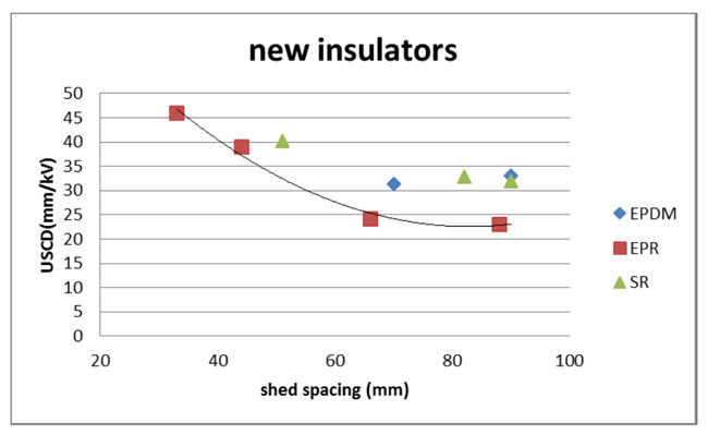
Quick flashover tests are also useful to get indications about optimized insulator profile. For example, Fig. 7 plots the test outcomes of USCD vs. shed spacing, highlighting that the smaller the inter-shed distance, the higher the USCD required (as expected).
Results confirm that salt fog and in particular tests with the quick flashover method are useful to get indications about pollution performance of composite insulators. Incidentally, the quick flashover method is much faster (and less costly) than the standardized method for ceramic insulators. However, information about the performance of composite insulator under the quick flashover method yields only preliminary indications for design, as may also be derived from ageing tests and some service experiences.
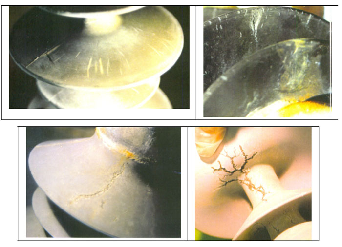
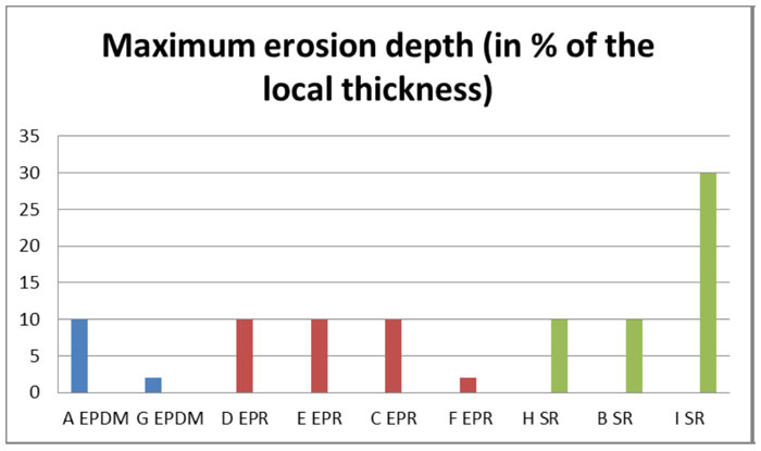
With particular reference to ageing tests, these were carried out energizing the insulators in Table 1 at a test voltage of 70 kV in DC, corresponding to an average USCD of 49 mm/kV (or 44% higher than the average value suggested in Fig. 5 for a new insulator). In spite of the above margin between the voltage resulting from the quick flashover method and the ageing test voltage selected, degradation of the insulators occurred following these tests, as shown in Fig. 8. Quantification of degree of erosion is shown in Fig. 9, which reports degree of erosion of housing, expressed in % of local thickness after 3000-hour DC ageing.
Results confirm that, for composite insulators, it is not only necessary to select an appropriate USCD to avoid flashovers in service (same as for ceramic insulators), but also to take additional safety margins to limit, as much as possible, degradation in service (i.e. by selecting USCD values that guarantee very low leakage currents).
Solid Layer Test Experience
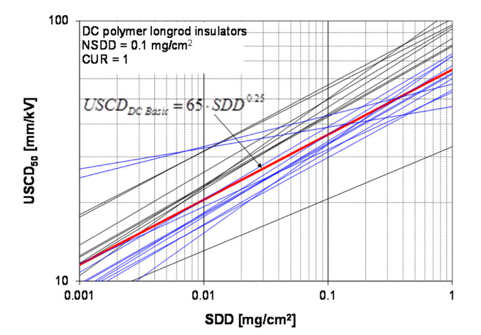
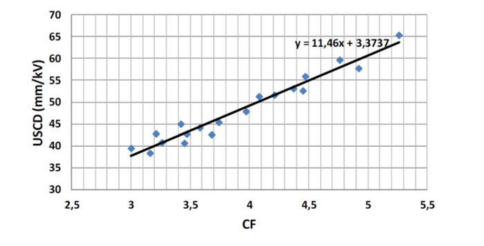
Results obtained on composite insulators with partially or fully suppressed hydrophobicity are reported in Fig.10. Comparison is also made with the curve proposed for design. The evident wide dispersion in data may be accounted for by varying degrees of hydrophobicity transfer/recovery during testing. Another reason could be difference in test procedures, in absence of a standardized procedure. Finally, part of the difference may derive from differences in geometry, as shown in Fig. 11, which reports necessary USCD as a function of creepage factor (i.e. ratio of creepage distance to arcing distance).
An attempt to set-up some agreed procedure was made, basically following IEC 61245, after having pre-conditioned the insulator by dry kaolin. Accounting for the HTM characteristics of insulators during the test was done by prescribing different times between coating the insulator by the pollution slurry and allowing for insulator recovery. Variation in flashover voltage given this recovery time was, however, limited (i.e. 10 to 20%). The investigation mainly covered AC voltage. The few tests made under DC voltage gave a USCD50 of about 27 mm/kV at SDD=0.3 mg/cm2 (i.e. in the lower range in Fig.10).
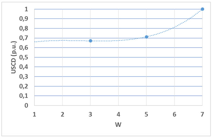
An attempt to arrive at a procedure to simulate different hydrophobicity status was made by contaminating insulators with different types of slurry. Different wettability conditions were obtained adopting different non-soluble materials in the slurry: kaolin to simulate limited recovery (i.e. W close to 7), kieselguhr with a small kaolin percentage to obtain a wettability class of 5 to 6, without allowing recovery time after contamination, and from 1 to 3 by allowing a period of recovery of a few days. The tests were performed in AC, however it can be assumed that, in p.u., results also apply to DC. Dependence of USCD on wettability level is shown in Fig.12. It is interesting to note that polymeric insulators provide high performance even when they have lost part of their hydrophobicity (i.e. up to wettability level of about 5).
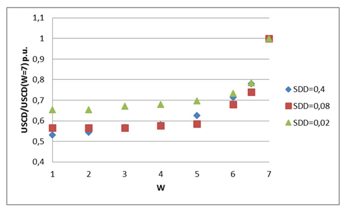
The above trend can be explained considering that for high hydrophobicity conditions the flashover process along the surface becomes more difficult and the preferential path becomes the one across air, thus with a much more limited influence of pollution severity and insulator geometry characteristics (including the diameter as assumed in.
Design of Composite Insulators for Contaminated Environments
As shown above, the issue of pollution performance of polymeric insulators is complicated mainly because of its dependence on evolving surface conditions. Moreover, even if representative short-term pollution performance could be established, its applicability to design would be questionable since the main challenge for composite insulators is not to prevent flashover but rather to avoid or delay deterioration in service. As a consequence, prevailing opinion is that design of polymeric insulators should presently be made mainly based on field experience. It is interesting to quote the opinion of the WG Members:
“Although there is some positive experience with validation by testing of traditional glass and porcelain insulators, this experience is mainly with pollution withstand tests where the degree of over-design is unknown. Any such experience is mainly lacking for composite insulators and the problem is accentuated by the continuing rise in system voltages where over-design may result in unrealistic insulator lengths or heights. Hence for this first edition the verification of a chosen insulator solution by testing is entirely subject to agreement.”
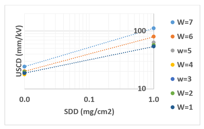
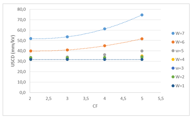
In spite of the limited knowledge on performance of composite insulators under DC voltage, an attempt has been made to give preliminary design indications based on available information. Specific software was set-up to obtain such indications for both ceramic and polymeric insulator designs. The software covers both solid layer and salt fog conditions. In the following examples, only the solid layer case is examined. Firstly, required insulation performance to be taken into account during design has to be established. Pollution performance of composite insulators is classified based on limited available laboratory and field experience but to be optimized in the future on the basis of systematic tests. Assumed trend of USCD with SDD is reported in Fig.13, with reference to insulators having an average diameter of 250 mm and a creepage factor of 2. Influence of insulator geometry, in terms of average diameter and creepage factor, is shown in Figs. 14 and 15 respectively (SDD=0.1 mg/cm2).
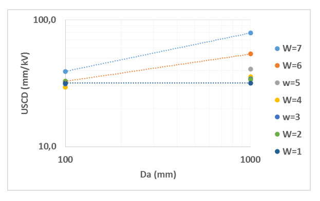
Once assumptions are made on insulator strength and expected pollution severity, necessary specific creepage distance compatible with performance required can be evaluated. For example, calculations were performed assuming:
• ceramic insulators with 250 mm average diameter and CF=3.2;
• composite insulators with 100 mm average diameter and CF= 3.2, after service with wettability level W=6;
• maximum pollution severity (2% probability) of SDD=0.1 mg/cm2;
• 10 critical wetting events and only 100 insulators at the assumed maximum contamination for the entire line.
Fig. 16 shows number of flashovers that can be expected for ceramic (black line) and composite (red line) insulators as a function of selected USCD.
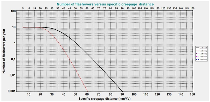
Assuming it is acceptable to have 1 flashover per year for the line, 50 mm/kV would be necessary for ceramic insulators while only 35 mm/kV would be sufficient for composite insulators. However, it should also be taken into account that composite insulators need to perform far from flashover conditions in order to limit leakage currents that could lead to deterioration. This can be achieved by requiring higher margins for composite insulators, e.g. requiring some number of flashovers every 10 years versus perhaps 1 flashover per year for ceramic insulators as well as by specifying a USCD for composite insulators, such as 45 mm/kV, close to that for ceramic types.
Conclusions
• Performance of polymeric insulators at a given pollution severity is not given by any unique value since it depends on surface condition, which varies during the life of the insulator.
• In spite of different proposed pollution test methods to be adopted, there is not yet agreement on any method, being at the same time representative, reproducible and repeatable.
• Investigation up to now has mainly covered line insulators. Information on influence of insulator geometry on required USCD at different hydrophobicity levels is still scarce, especially for DC.
• Attempts to classify different influences on the basis of limited available quantitative/qualitative information has been made but needs to be optimized on the basis of results of forthcoming new investigations.
• Application of ad hoc software permits indications of required creepage distance for composite insulators.
• Design of composite insulators should take into account not only the need to limit flashovers but also to contain leakage currents to very low values, even when most of their hydrophobicity has been lost. Calculations indicate that, based on this criterion, required USCD of composite insulators can be close to that of ceramic insulators.
References
[1] A. Pigini, R, Cortina, M. Marzinotto,G. Lagrotteria “Pollution tests on composite insulators: the Italian experience” ISH 2015
[2] P.J. Lambeth “Variable-voltage application for insulator pollution tests” IEEE Trans. on Power Delivery, Vol. 3, No. 4, Oct., 1988
[3] G. P. Fini. G. Marrone, F.Gallucci, A. Pigini “Field expereience and laboratory ageing tests on composite insulators for overhead lines”, L’Energia Elettrica N.1, 1983.
[4] S. Bossi, A. Pigini, G.P. Fini, A. Porrino, Channakeshava, N. Vasudev, M. Ramamoorty “Study of the performance of composite insulators in polluted conditions” Cigre Report 33-204 1994 session
[5] IEC doc 36/303/NP Future IEC 60815-4 Ed. 1.0: Selection and dimensioning of high-voltage insulators intended for use in polluted conditions – Part 4: Insulators for d.c. system
[6] CIGRE WG C4.303 “Outdoor Insulation in Polluted Conditions: Guidelines for Selection and Dimensioning, Part 2: The DC Case” CIGRE Brochure 518
[7] CIGRE WG C4.303 “Artificial Pollution Test for Polymer Insulators- Results of Round Robin Test” CIGRE Brochure 555
[8] Fuzeng Zhang, Xiaolin Li, Bing Luo, Liming Wang, Zhicheng Guan “Influence of composite insulator shed design on flashover voltage”
[9] Liang Xidong, Wang Shaowu, Huang Lengceng, Shen Qinche, Cheng Xueqi“Artificial pollution test and pollution performance of composite insulators” Paper 4.337.P2 SEDOC
[10] A. Pigini, R. Cortina ”Evaluation of the performance of polluted insulators under DC: a statistical approach” ISH 2011“