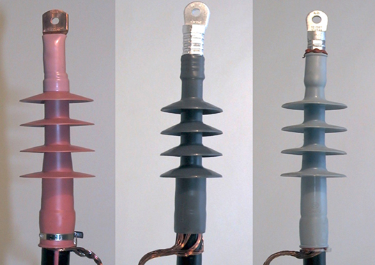
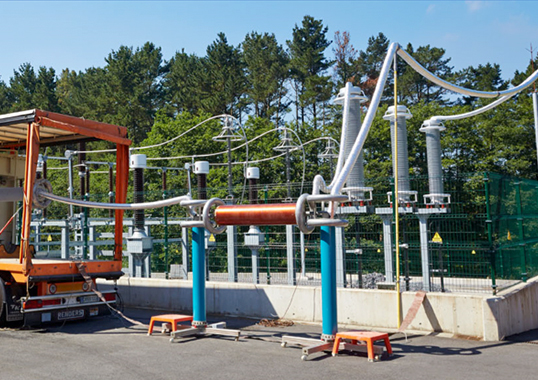
One of the biggest challenges in testing power cable systems is finding the optimal balance between highest efficacy and lowest risk of damage. In this edited contribution to INMR, Paul Leufkens of DNV Energy in the United States offers an assessment of recent developments in methodologies, relevant standards and technologies in the field of testing power cables and accessories.
Generic MV & HV Cables & Accessories: Developments at IEC & IEEE
Over the past decades, the volume of power cables being produced has been increasing by 8 to 10% each year. While most of these new cables are for distribution networks, annual growth in application of HV cables has recently been in the double digits. Key issues driving this trend are growth in the renewables sector and demand from within urban areas where, due to land limitations, cables are being installed in preference to overhead lines. Apart from volume, lengths of cable systems are also increasing and HV networks that cover hundreds of kilometers are no longer rare. Such longer lengths create challenges not only for the factory but also when it comes to on-site testing. Lengths of distribution networks are increasing as well, often covering 15 to 20 km.
In regard to applied insulation material, there is now a clear trend to use of only polymer insulated cables. Polymeric materials such as polypropylene (PP) have been developed and are being used for HVDC cables. New materials present new challenges, especially in terms of diagnostic assessment, such as dielectric losses.
Modern day production processes for power cables and their accessories are well-controlled and one of the main product philosophies is being ‘fit for purpose’. For example, insulation thickness is kept to the minimum necessary to reduce costs. But this approach comes with the downside that almost every workmanship error will eventually lead to a system defect.
Within the standards and guidelines there has not been a lot of change over the past decade and these continued to be based mainly on withstand testing only. Although diagnostics are recommended, no threshold values are mentioned. Within CIGRE, several working group activities have been undertaken both for MV and HV cables. A new brochure, TB841, has been published that discusses alternative methodologies for after-laying testing of HV and EHV cables. Although the brochure was not the original goal, it nevertheless provides a valuable overview of which methods can be applied. For MV networks, an active Working Group on MV cable asset management (B1.58) closed in 2022. This WG aimed to propose asset strategies to be applied on several type of cables (i.e. polymer, paper, mixed) for commissioning, after-repair and maintenance testing. All test and diagnostic methods, i.e. the complete toolbox, were to be described along with a pros and cons analysis of each, apart from a section dedicated to asset management.
MV Off-Line Site Testing, Diagnostics & Monitoring
Underground MV power cables have become an important component of modern distribution networks. Experience from network operators has shown that localized degradation, cable joints and terminations often constitute the ‘weak spots’ in these systems, apart from factors such as ageing, water ingress, inadequate workmanship and utilization of inappropriate or defective accessories. Hence the need to deploy testing and diagnostic techniques on both new and serviced-aged MV cable systems to ensure highest possible reliability, as outlined in guidelines and standards such as the IEEE 400 series and IEC 60502-2.
The standards today are written mainly for cable withstand testing. While there is some guidance on diagnostic methods for TanDelta and partial discharges (PD), this is either limited or outdated. Looking to the IEEE 400.2 TanDelta tables, for example, one can question: ‘will the cables from 2015 still have the same recommended trending limits as cables installed in the 1980s and 90s? Also, looking to PD diagnostics on paper-insulated cables, can any threshold values be defined since this type of cable is not designed to be PD-free?
Withstand tests typically require application of continuous voltage at a prescribed voltage level (normally above nominal operating voltage) for a prescribed time. The cable system under test will either ‘Pass’ or ‘Fail’. If the cable system fails, i.e. breaks down during testing, it will either be repaired or replaced. A withstand test can be classified either as a simple withstand test or a monitored withstand test. The latter differs from a standard withstand test in that other parameters are also monitored e.g. dielectric losses, leakage current or partial discharges. Fig. 1 shows a generic schematic of a monitored withstand test (MWT).
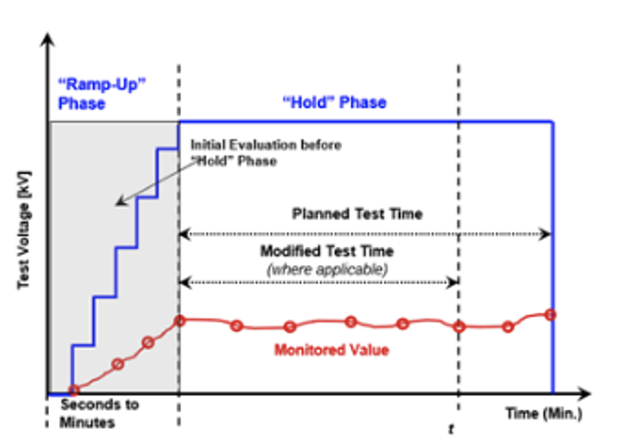
As a basic principle, a simple or monitored withstand test is designed to consistently overstress a cable system to some acceptable risk level. As such, for a withstand test to be effective, it must include the following fundamental elements: defined voltage exposure, repeatable voltage exposure and a well-defined failure rate.
The most commonly used excitation voltages are VLF (very low frequency), either sinusoidal or cosine-rectangular, followed by DAC (damped AC). In some cases, power frequency or near power frequency is used and, in rare cases, a soak test is also performed. Use of DC voltage on extruded cable systems for withstand testing has been discouraged by IEEE 400.1, ICEA S-94-649-2004 and IEC 60502-2.
Withstand testing for medium voltage cable systems is performed mainly in the context of commissioning/acceptance/electrical testing after installation of new cable systems. The goal of a withstand test during commissioning is to ensure the cable system is safe to energize and for quality control purposes. The impact of cable failure during testing is considerably lower and repairs can be made relatively quickly and cost effectively compared to in-service failures and resulting unplanned (emergency) outages and repairs. Additionally, a withstand test can also be performed on aged cable systems.
It should be noted that in the case of aged cable systems monitored withstand testing is recommended above simple withstand testing. Moreover, some industry guidance/standards recommend reduced test voltages relative to cable commissioning contexts. The decision to conduct withstand testing should always weigh the cost of failure during testing versus the cost of in-service failure and subsequent unplanned outages and repairs. The main disadvantage for withstand testing of aged cable systems is that there is a risk of inducing failure during the test, especially for cables that are already degraded. This could cause additional complications in aged cable systems due to issues such as lack of spare components, difficult accessibility for repairs, outage availability, etc. Additionally, in cable systems that are already degraded, residual life could be reduced by applying withstand testing with a voltage higher than nominal voltage.
Generally, it can be stated that simple withstand testing will give a certain degree of confidence when putting a cable into operation. However, not all defects can be detected during a simple withstand, no matter what excitation voltage is used. Applying diagnostic methods as in a monitored withstand or diagnostic context helps ensure higher reliability of the cable system.
Looking to diagnostic methods on MV cables, these can differ in core and context specific methods. Core methods are VLF tan delta, TDR (time domain reflectometer), PD testing and jacket testing. These methods are suitable for almost every cable type. Despite lack of consensus on acceptance criteria for most of these, such methods are well known and documented. Modern devices are easy to operate and the core methods should be considered as the basic toolbox for cable testing and diagnostics, providing the user with a fast and reliable result.
The purposes of context specific methods are multiple and these can be recommended during a commissioning test for baselining purposes, or at higher level of diagnostics or troubleshooting to increase accuracy of the measurement. Typically, these context specific measurements are applied on critical system infrastructure such as in nuclear power plants. These methods should be considered an ‘added value’ to the core methods. Due to their specificity, some may require more experienced operators in order to obtain exploitable results. Context specific methods include FDR (frequency domain reflectometry), neutral resistance measurements, FDS and TDDS (frequency domain spectroscopy and time domain dielectric spectroscopy), insulation resistance measurements, PDC (polarization, depolarization current measurement) and conductor resistance measurements.
Two main core methods being widely applied are VLF TanDelta and PD testing. VLF TanDelta measurements were originally intended to detect water trees in degraded polymer insulated cables. However, as cables being installed have become more resistant to water tree growth, especially long bridging water trees, the purpose of VLF TanDelta measurement has been changing as well. Experience gathered over the past decades is moving from a global measurement to a local measurement. Comparing phases with one another makes it possible to identify local issues, however these are not localized. Still, this gives operators important information about the reliability of their networks and is extending application of VLF TanDelta measurements to mixed cables systems.
PD testing on MV cables is broadly performed (mainly off-line). A proper test strategy should be applied to:
• Maximize the probability of identifying PD inducing defects (reducing risk of false negative results);
• Discriminate such defects internally and from noise (reducing risk of false negative and false positive results);
• Localize identified defects (allowing for targeted repairs);
• Allow for condition assessment that can allow for pass/fail assessment or potentially deferred investment, ideally through relating results to in-service (operating) conditions.
A wide range of offerings exist among PD equipment vendors and service providers, ranging from ‘black-box’ type approaches with proprietary algorithms only used by service providers, to fully customizable and adaptable systems requiring high levels of expertise, to ‘push-button’ type boxes which in principle can carry out measurements for unskilled users.
To obtain a better understanding of how to deal with all such options and of their impact on accuracy and performance of field PD assessment, a good starting point is to understand the basic technical considerations that most influence the outcomes of a PD measurement.
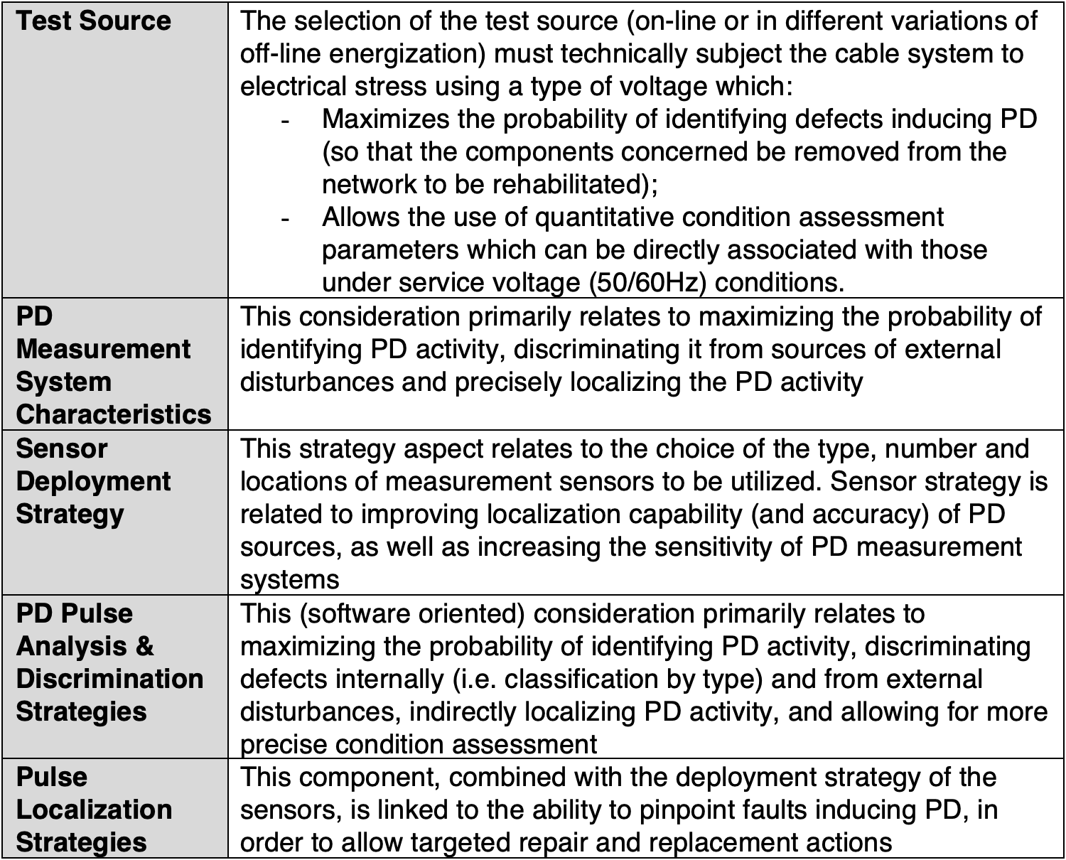
The most commonly used systems for MV networks are single-ended PD measurement systems and use of either DAC, VLF CR or VLF sinusoidal excitation voltage. There is lack on guidance when looking to trending limits, especially for aged cable systems. Apart from user experience and recommendations, there is no standard. In addition, as for the differences between test voltage sources, there will likely never be general guidance on acceptance levels.
The numbers of monitored MV cable systems currently is still low. Demand is rising but, apart from the issue of cost, there are also some technological hurdles, as reviewed in Table 1. With on-line PD methods, the chance of false positives or false negatives is still high, which is not acceptable to most end-users.
Finally, with all measurements that can be performed for both withstand testing, diagnostic testing or monitoring, proper data handling is also of importance. The need for an asset management system/software is constantly increasing, not only in terms of handling measurement data but also in regard to such data as age, location, number of faults, etc. In the past, diagnostic measurement was limited and could be treated differently. Now, with the current broad use of diagnostics methods by utilities, only by applying proper asset management, guided by software, will it become possible to increase the availability and reliability of power cable networks.
HV Cables: On-Site Testing & Diagnostics
Since reliable energy transmission and distribution are fundamental for every economy, the various aspects of maintaining quality control for newly installed as well as in service power cables is of great importance. Key questions for power utilities in regard to maintaining/updating internal procedures for reliable cable network operation include:
1. How best to perform, in a sensitive yet non-destructive manner, detection of poor workmanship defects in newly installed HV cable circuits?
2.How best to perform non-destructive diagnostics of HV cable circuits in service to determine their actual condition?
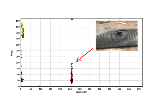
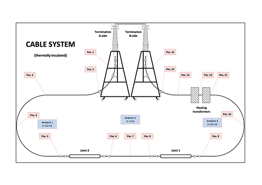
Over the past 30 years of testing distribution and transmission power cables, different test methods have been introduced and are currently in use, including: continuous AC resonant (ACR), damped AC (DAC) and very low frequency (VLF). From the start of offshore wind farm installations, such onshore methods have also been applied for testing offshore power cables. Unfortunately, considering the greater need for quality control for offshore HV cables and for long onshore HV cables, all these methods can present challenges, as illustrated in Table 2. Different studies during the last 20 years have shown that regarding voltage stresses, partial discharge occurrence and dissipation factor measurement, differences can exist between the ACR and DAC methods. Nonetheless, when used by experts, both are a valuable tool for assessment. It has been documented in recent publications that wheb testing transmission power cables, DAC after-laying and diagnostic testing allows sensitive PD detection. Moreover, using DAC calibrated PD detection is possible on-site, with background noise below a few tens of pC.
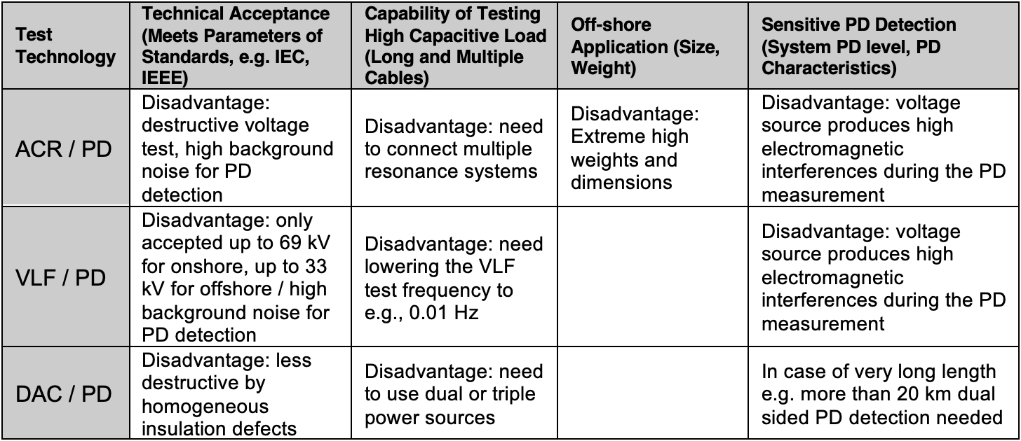
IEC standards such as 60840, 62067 and 63026 place emphasis on manufacturing and therefore most of their content deals with testing aspects in the factory. An up-to-date description of methods for on-site testing of high voltage cables has long been necessary but is taking place only slowly, especially on alternative on-site test methods for ACR. Moreover, most standards provide no up-to-date guidelines regarding field experience in after-laying and maintenance testing of cable circuits. CIGRE’s TB 841 is not standard but rather a recommendation and provides recent methods and experience. Traditionally recommended over-voltage testing with a binary test outcome, i.e. ‘breakdown’ or ‘no breakdown’, will reveal major defects. But PD detection should be added when possible and a check should always be made for the risk of igniting faults that would not have occurred under operating voltages.
Some TSOs are in the process of developing or have already developed their own more dedicated procedures to test newly installed cables. These procedures are based on service experience and selected IEC documents as well as on existing international standards made in cooperation between power companies, cable manufacturers and testing organizations. These guidelines have come to represent the current state-of-the-art for non-destructive methods for both after-installation and maintenance testing and diagnostics.
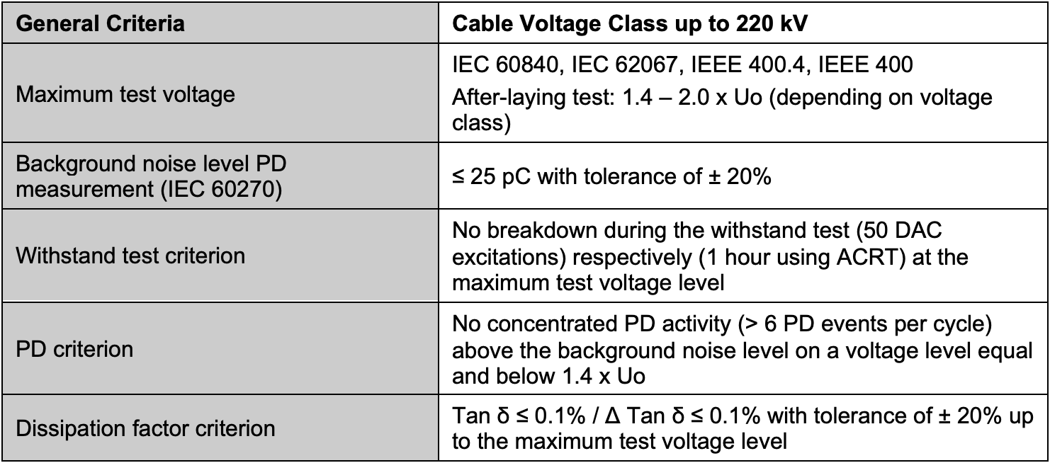
Introduction of on-site PD monitored voltage withstand testing of power cables has opened the possibility of reproducible conditions for PD detection. Based on research and about 20 years of testing of power cables up to 230 kV at numerous different 3rd parties offering after-laying testing, the following parameters could be recommended as general criteria for DAC and ACRT testing to determine if a cable has passed the test and is sound for operation (see Table 3).
Submarine Factory & On-Line Cable Testing
Submarine cable systems differ in several respects from underground cable systems. Among the more notable differences are manufacturing and delivery lengths being much longer as well as use of factory-made joints. Manufacturing lengths typically depend on the maximum time an extrusion line can run before it must be cleaned. This converts to maximum length through the relationship between volume that can be extruded per unit of time. Volume of insulation that can be extruded per unit of time relates mainly to voltage class and cable cross-section, i.e. it generally takes more time to extrude a kilometer of cable of high voltage class or large cross-section. That means that typical manufacturing lengths of the highest voltage classes can be 10-20 km, whereas much longer lengths can be extruded in one run when the voltage class is lower and/or cross-section is smaller. Mass-impregnated cables are produced batch wise, where length depends on size of the impregnation vessel. The focus below is on extruded cable technology
Delivery lengths that are finally loaded onto the installation vessel are much larger than individual manufacturing lengths. For that reason, manufactured lengths are jointed together using so-called factory joints to form one large delivery length. Maximum delivery length is determined largely by factory storage capacity, i.e. size of turntables, and also by maximum load the vessel can handle and safely transport. Maximum delivery lengths are defined by the size and maximum weight capacity of the vessel’s turntables. The outer diameter and height of such turntables define the volume while the vessel’s properties define the maximum weight of the stack. Diameters of the turntables in most modern vessels can reach 20-25 m or more and the maximum weight the different vessels can carry sometimes surpass 10,000 tons. As such, maximum delivery lengths of power cables, while greatly dependent on cable and vessel type through their size and weight, nowadays easily reach well over 100 kms. Looking to the future, lengths of 150 km or more seem realistic. These different considerations about length can have profound implications on testing.
While cables are available in many different types, it is possible to categorize them according to certain hierarchies. Firstly, AC cables can be divided into 1- and 3-core types. The 3-core cables share the same armor package and the 3 cores can be installed in a single lay. By contrast, single core AC cables need 3 separate laying campaigns per phase. DC cables need only two poles (plus and minus) and, although often laid in a bundled fashion, the two poles are still two independent separately armored cables.
AC cables have a limitation in useful length between two connecting stations since they generate capacitive current. Depending on voltage class, such lengths are roughly maximized to between 50 and 150 km. By contrast, DC cables do not face this limitation and can attain route lengths of several hundred kilometers. This means that testing DC cables can face practical challenges due to the possibility of their significantly increased lengths.
AC cables (including submarine type) have been implemented at 500 kV whereas DC cables are commonly installed and projected at a level of 525 kV. Route lengths can be several hundreds of kilometers and it seems probable that the 1000 km barrier will eventually be surpassed using DC technology. It is clear that probability of a small defect in a cable system increases with its length. As such, testing, as one component of quality control, becomes very important. Nevertheless, it is also important to note that no testing can replace good workmanship and proper quality control of all steps – from sub-supply, to design, to installation. In this context, testing is rather an integral part of QA and QC.
Moreover, testing can also be categorized into three hierarchal classes: qualification testing, manufacturing and installation testing, and on-line testing & monitoring. Passing a pe-qualification test (PQ) or the addition of an extension of it (EQ) means that the manufacturer of a certain technology can supply such cable systems on a commercial basis, covered by such standards or recommendations. Holding a successful type test (TT) certificate means that the supplier can provide a certain technical solution on a commercial basis that meets the performance characteristics for an intended application, as covered by the standards or recommendations. These tests are conducted on a limited length of cable (tens to above 100 m) and only a small number of accessories. Such tests can be viewed as a student having passed a university exam but with no guarantee that they will do a good job every single day of the week in their upcoming career.
Manufacturing and installation tests cover every single meter of cable and every accessory. Such tests are routine tests, FAT (factory acceptance test) and possibly also a harbour test. The extent of these tests depends on cable system type as well as on the contract. Sample tests are performed on a sample of the projected cable length and number and serve to ‘measure’ the quality of design at certain points in time along the project line. The harbour test is intended to hand over responsibility for the project from manufacturer to installer in cases where these are different entities.
The challenge in testing long submarine cables comes with the long manufacturing lengths and very long delivery lengths. Typical extruded AC cables are routine tested at 2.0-2.5 U0, the lower multiple representing the higher U0 voltage class. The historical reason for this was that one did not want to exceed certain electric field thresholds above which the cable would age in a different way than from service. In regard to long cable lengths, there is another reason that practically limits the test factor. The higher the test factor (and with that the voltage), the larger the capacitive loading current. The test equipment must be able to deliver that. Originally, this problem was self-limiting because cables with the highest voltage classes often had the shortest delivery length due to the inherent issue of capacitive loading in service. This challenge has now returned with the introduction of extruded DC cables.
The recommendations state that the manufacturing lengths are to be tested with an AC voltage such that the AC stress is 20 or 23 kV/mm at the conductor screen. The challenge increases given the realization that the recommendation asks for an AC and PD screening test of the factory joints, if applicable. The term, “if applicable” was added because the challenge now becomes clear. Several manufacturing lengths are being factory-jointed together and, if possible, each joint shall be locally PD-measured. This means that the joint and the cable lengths before and after the joint shall be put on voltage, even though for short duration. The last joint, adding the last manufacturing lengths to the previous sections, make up the full delivery length.
HVDC cables having delivery lengths of 100 to 150 kms or more and tested at 23 kV/mm places severe challenges on the AC resonant test equipment, which must become very large. For example, the capacitive loading current during testing of a large cross-section 525 kV cable, tested in the interval 400-440 kVac, becomes around 1 kA if fed at one end and half that value if fed from both ends. These values are significant and care must be taken to ensure that the cable sheath can carry the current. Similarly, the heat generated in the cable stack also has to be considered.
One way of overcoming this challenge is to allow for other testing methods. TB 852, for example, offers a different way of addressing the QC of the joint using X-ray inspection. Another emerging technology is acoustic detection and in-line ultrasonic sensing of extruded core is a sometimes-utilized technology. Moreover, based on that technology where the cable is moving through a static head with ultrasonic sensors, another technology has now been developed as well, i.e. keeping the object fixed and static, while the ultrasonic sensing head is moving instead. Such technology could prove particularly useful in controlling quality of the factory joint insulation and its interfaces. Ideally, one could then limit size of the AC resonance test set by optimizing it only for testing manufactured cable lengths. Alternatively, accept the maximum length that the AC test resonance set can handle, utilizing AC and PD testing up to that length, and rely on acoustic sensing for the joints after that length.
Installation tests can be divided into two categories as well. One category summarizing the tests during installation and the second the classic after-installation test. The after-installation test for AC cable systems is again limited to the maximum route length specific to the voltage class. PD tests are then typically performed locally on the accessories. Obviously, there is a need for a mobile resonance or DAC set if the test is not performed by connecting to the grid.
Lately the question has arisen whether one should perform an AC after installation test on installed underground extruded DC cable systems (possibly including local PD tests on the prefabricated accessories). Considering the inherently long lengths of DC cable systems, the AC test set-ups become very large, as explained above in relation to factory testing. There is as yet no experience relating the effectiveness and therefore the benefit of such AC testing on performance of extruded DC cable systems. The complexity of this test must therefore be weighed against its perceived effectiveness. Clearly, without much experience on what is being gained, the choice becomes less technical and more economic or of a risk management nature.
Obviously, if one could measure partial discharges under DC voltage online, one would have the perfect monitoring tool. But the challenges here are significant. Electrical noise levels of the outdoor system are often high and the repetition rate of the discharges are inherently much lower under DC than under AC voltage. Nonetheless, research has been pushing progress in addressing that problem and, although not yet solved, this remains a distinct possibility in the future. CIGRE Working Group D1.63: Partial discharge detection under DC voltage stress will result in a Technical Brochure that summarizes the state-of-the art of the industrial practice of this phenomenon.
Cable systems these days are often equipped with an integrated fibre (FIMT) for temperature and acoustic sensing purposes. Although limited in sensing length, progress is being made to increase this. Acoustic sensing is mainly used to detect external damage or imminent such, whereas temperature sensing could preventively sense changes in the external thermal environment.
Finally, in regard to offshore windfarm cables, all the above remarks are valid for both interconnector cables and offshore wind export cables. They are also valid in some respects for array cables, but these are inherently shorter and have different design aspects.
Summary & Conclusions
The biggest challenge in cable system test methodologies is finding the right balance between efficacy and not damaging against a background of acceptable budget and realistically sized testing equipment.
When it comes to reliability of cables in general, there is much confidence in testing at the production location as being well-understood, controlled, effective and standardized. That is why users are looking for similar quality control for accessories and systems after installation.
Lengths of several hundreds of kilometers in HV networks are no longer rare.
Most commonly used systems for MV networks are single-ended PD measurement systems that make use of either damped AC or very low frequency excitation voltage. There is still lack on guidance when looking to trending limits of especially aged cable systems. Apart from user experience and recommendations, there is no standard and, as for the differences between the test voltage sources, there will most probably never be general consensus/guidance on acceptance levels. With all the measurements that can be performed for both withstand testing, diagnostic testing or monitoring, proper handling of data is also of utmost importance. There is a growing need for an asset-management system/software that not only handles the measurement data but also includes key statistics such as age, vintage, location, number of faults, etc.
Studies by different parties over the past 20 years have shown that there are some differences between ACR and DAC methods in regard to voltage stresses, partial discharge occurrence and dissipation factor measurement. Still, both methods, when used by experts, are a valuable assessment tool. Traditionally recommended over-voltage testing with a binary test outcome, i.e. ‘breakdown’ or ‘no breakdown’, may reveal major defects. But PD detection should be added where possible and a check should always be made of the risk to ignite faults that would not have occurred under operating voltages,
As concerns submarine factory and online cable testing, maximum delivery lengths of cable depend greatly on the cable and vessel type through their size and weight but can now easily reach well over 100 kms. This will likely rise to 150 km or more in the future. The recommendations state that the extruded DC cable manufacturing lengths are to be tested with an AC voltage such that the AC stress is 20 or 23 kV/mm at the conductor screen. The challenge increases when realizing that the recommendation asks for an AC and PD screening test of factory joints, if applicable. Testing of the last joint, adding the last manufacturing lengths to the previous ones making up the full delivery length, places severe demands on the AC resonant test equipment, which needs to be very large. Other means, such as acoustic screening methods, might be a tool for future development.
All insulation defects resulting from installation that might reduce the system quality under AC will produce PD and that is one way to identify them.
References
[1] E. Gulski, R. Jongen, J. Parciak, J. Sieminski, “Modern Methods for Quality- and Condition Assessment of High Voltage Cables” 2020, VDE VERLAG GMBH, Berlin, Offenbach, ISBN 978-3-8007-5353-6.
[2] Smit J, van Riet M, Staarink B, “Non-destructive after laying test with PD localization”, Jicable 2019, paper D3-4
[3] IEC 60840: Power cables with extruded insulation and the accessories for rated voltages above 30kV up to 150kV Test methods and requirements;
[4] IEC 62067: Power cables with extruded insulation and the accessories for rated voltages above 150kV,
[5] IEC 63026: Submarine power cables with extruded insulation and their accessories for rated voltages from 6 kV (Um = 7,2 kV) up to 60 kV (Um = 72,5 kV) – Test methods and requirements, 2019;
[6] IEEE 400-2012: Guide for Field Testing and Evaluation of the Insulation of Shielded Power Cable Systems Rated 5 kV and Above;
[7] IEEE 400.4-2015: Guide for Field-Testing of Shielded Power Cable Systems Rated 5 kV and Above with Damped Alternating Current Voltage (DAC)
[8] HD 632 S2 (CENELEC): Power cables with extruded insulation and their accessories for rated voltages above 36kV (Um=42kV) up to 150kV (Um= 170kV);
[9] UK Power Networks, ECP 11-0006, Engineering Commissioning Procedure, ECP 11-0006, HV insulation testing 2018;
[10] IEEE 400.3-2006: Guide for PD Testing of Shielded Power Cable Systems in a Field Environment;
[11] IEC 60270: Partial discharges measurements;
[12] IEC 60885-3: Test methods for partial discharges measurements on lengths of extruded power cable;
[13] IEC 60060-3: High Voltage test techniques Part 3: Definitions and requirements for on-site testing;
[14] Cigre TB 420: Generic Guidelines for Life Time Condition Assessment of HV Assets and Related Knowledge Rules, 2010;
[15] E. Gulski, R. Jongen, B. Quak, J. Parciak, A. Rakowska, Fifteen Years Damped AC Testing and Diagnosis of Transmission power cables, Jicable 2019, paper D3-1.
[16] Leufkens P, Gulski E, Jongen R, Damped AC for Commissioning & Diagnostic Testing of HV Cable Circuits, Proceedings of INMR World Congress (INMR 2019), 20-23 October 2019, Tucson, Arizona, USA, ISBN: 9781713803256;
[17] P. Cichecki, Testing and Diagnosis of High Voltage and Extra High Voltage Power Cables with Damped AC Voltages ISBN: 978-83-952726-0-8;
[18] F.J. Wester, Condition assessment of power cables using partial discharge diagnosis at damped AC voltages, ISBN 90-8559-019-1;
[19] CIGRE: Technical Brochure 841 After laying tests on AC and DC cable systems with new technologies, 2021
[20] PTPiREE, Frame instructions for exploitation of power cables up to 110 kV, 2011;
[21] PSE, Power cable lines 220 kV and 400 kV, 2020;
[22] M. Jeroense, Quality Control of HVDC Cables – The next industry challenge, JICABLE 2019, D8-3;
[23] TB 852, Recommendations for testing DC extruded cable systems for power transmission at a rated voltage up to and including 800 kV, CIGRE, 2021;
[24] S. Sutton, P. Willmott, “Determining Cables Metrics Using 3D Ultrasonic Scanning”, CIRED 2017, Paper 0418;
[25] IEEE 400.2-2013: IEEE Guide for Field Testing of Shielded Power Cable Systems Using Very Low Frequency (VLF) (less than 1 Hz).
[26] IEC 60502-2-2014:Power cables with extruded insulation and their accessories for rated voltages from 1 kV (Um = 1,2 kV) up to 30 kV (Um = 36 kV) – Part 2: Cables for rated voltages from 6 kV (Um = 7,2 kV) up to 30 kV (Um = 36 kV)
[27] Neetrac CDFI, Phase 2, Cable handbook 2016 – Chapter 9 Withstand testing
[28] ICEA S-94-649-2004: Concentric Neutral Cables Rated 5 Through 46 kV
[29] R.Probst, F.Petzold, H.Putter: Excitation Voltages for Partial Discharge Diagnostics on Medium Voltage Distribution Cables, IEEE T&D Denver 2018
[30] H.Putter, F.Petzold, P.Legler: Offline PD diagnostics using several excitation voltages, CIRED 2017 Glasgow, Paper 0049
[31] H.Putter, F.Petzold, D.Götz: Innovative Solutions for On-site Diagnosis of Distribution Power Cables, IEEE T&D Orlando 2021, Paper 0041
[32] A.Lathouwers, P. Jansen, E. de Meulemeester: TenneT’s giant leap to be able to replace 140 substations within next 10 year, while in service and coming from different lay-outs, CIGRE Paris 2020, B3-104

