The externally gapped line arrester (EGLA) optimizes the positive characteristics of the oldest arrester design component – a series gap – and the newest arrester design component, namely the metal oxide varistor (MOV). Combining these two yields a significant improvement in line protection and reliability options for electric utilities. However due to the negative characteristics of gapped technology when used in series with earlier silicon carbide (SiC) arresters, the EGLA has sometimes experienced problems in user acceptance. This INMR article from 2014, contributed by Jonathan Woodworth, clarified the differences between the two alternative line arrester technologies and outlined the characteristics that make this design attractive for many line protection applications.
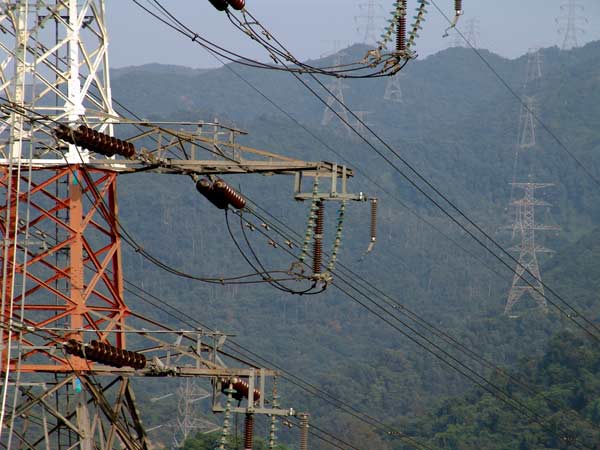
The name externally gapped line arrester came from the activities of IEC TC37 Maintenance Team 4. About 2001, the Japanese and the French National Committees introduced externally gapped arresters as a new work item for MT4 to deal with. After several meetings, the acronym EGLA was adopted to give this style of arrester easier reference. Also, the term ‘line’ was added since this arrester is most often applied for protection of distribution and transmission lines. As of April 2008, IEC TC37 MT4 is still actively working on a test standard for this design of arrester. The EGLA has been in use worldwide at many different line voltages and appears to find greatest usage in Japan, Korea, China, France, Italy and Brazil.
Application Overview
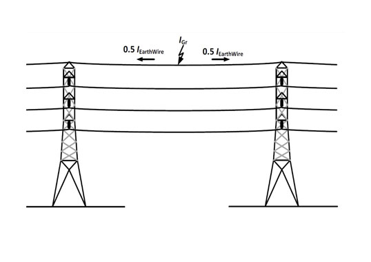
The most common application for these types of arresters is protection of lines. If used on a transmission line, they can be dimensioned so they do not operate when a switching surge is present but rather only conduct when a lightning surge appears. Applied on a shielded line (with an overhead ground wire) and where the arrester is used primarily to mitigate back-flashover of insulators, they can be dimensioned to be quite small since the energy handling requirement is not as demanding as for unshielded lines. When applied to unshielded lines, the EGLA’s size may need to be substantially larger to handle 100 percent of the lightning current. In all cases, application requirements drive the dimensioning of the arrester. It seems unlikely that this arrester will ever evolve to the point where it can be used to protect equipment unless there is a breakthrough in gap technology that eliminates front-of-wave spark-over issues. Such FOW issues are of course not applicable for the protection of self-restoring line insulation.
Fundamental Design Review
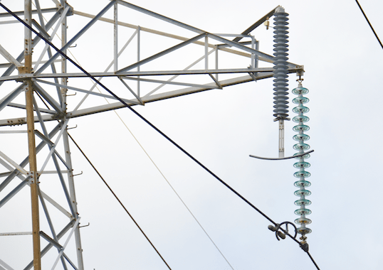
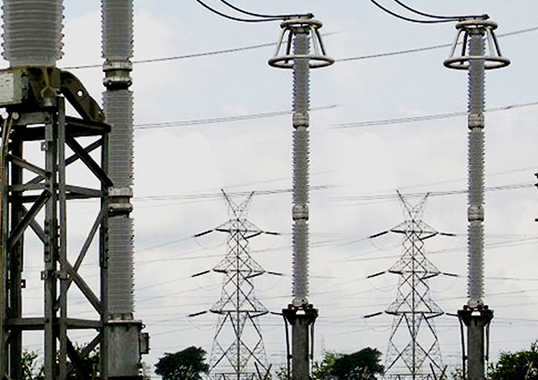
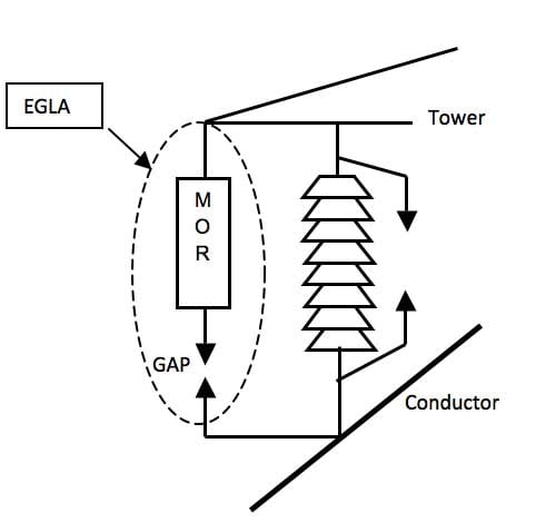
The EGLA has two basic components: the MOR and the gap. The MOR is a non-linear metal oxide resistor and has roughly the same characteristics as a standard MOV arrester. The gap is generally a single air gap in series with the arrester. It is important to note that each component of the EGLA is significantly different from earlier gapped arresters.
CLICK TO ENLARGE
Advantages of EGLA Concept
The gap section of earlier generation SiC arresters consisted of hundreds of components including many series gaps, parallel resistors, field shaping coils, etc. These were always enclosed in a housing and were a highly engineered component. By contrast, the gap in an EGLA has only two terminals.
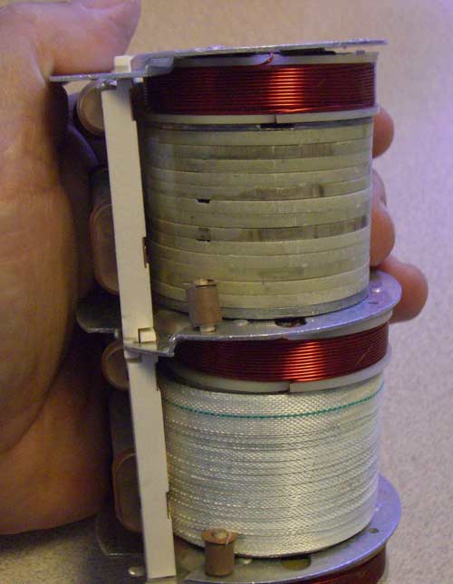
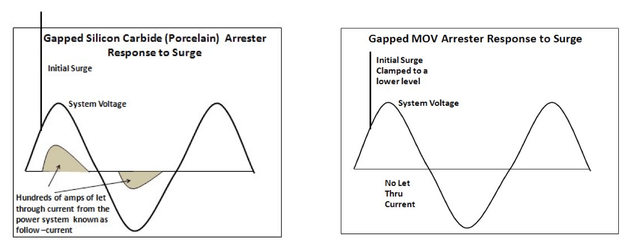
In the earlier generation SiC arrester designs, the gap section functioned as a switch that turned on at the moment of the surge and then turned off when the voltage across the gap was near zero. In this sense, the gap was used both for turning the arrester on and off. By contrast, the gap of an EGLA is used only for initiating an operation – not ending it. Instead, the MOR has assumed this function of ending the surge. Due to its superior nonlinear characteristics, the MOR has also eliminated a very negative attribute of the series gap known as follow current ageing due to power frequency current flow. This is because in old SiC gapped arresters, the MOR consisted of silicon carbide blocks used to limit the power frequency current that followed the surge through the arrester after impulse. These limited current levels protected the gaps from excessive damage and also made it possible for them to end the operation when voltage reached low levels. However, they also allowed enough current to follow through the arrester to degrade the gaps and gradually change their characteristics.
CLICK TO ENLARGE
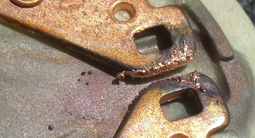
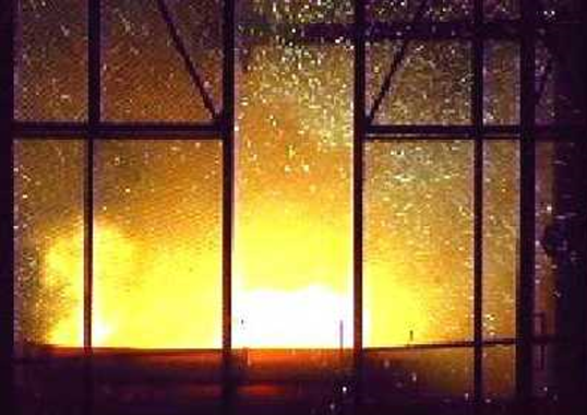
This photo provides a close up of the degradation of gaps in earlier generation series gapped arresters. In this example, the gap was in series with 80 other gaps at 500 volts each. This degradation was repeated 80 times in the 40 kV arrester and is due entirely to the follow current experienced during the service life of the arrester. Such degradation, however, does not occur in newer generations of EGLA since only lightning current passes through the gap. Therefore, the gap performance of an EGLA will not be compromised over its lifetime due to the fact that its MOR component eliminates the damaging follow currents experienced in by old SiC gapped arresters.
Design Benefits of Series Gap
1. Reduced MOR Housing Creep Distance
Since the MOR is in series with a gap, the voltage drop across the MOR and its housing during steady state operation is virtually zero. The most significant effect of low electrical stress on the MOR is that the housing does not need to have the same characteristics as a standard arrester, i.e. because of low long-term stress, the creepage distance of the MOR can be reduced. Since the MOR insulation is only called into duty during the 100 microseconds surge, it is possible that sheds are not even necessary.
2. Reduced Number of MOV Disks
Another significant benefit of the series gap is that the MOR can have a reference voltage 20-30 percent lower than the direct connect arrester design. The reference voltage need only be high enough to fulfill its function to switch off the arrester after the surge has passed. This means the turn on voltage of the MOR can be just a few percent above the system voltage it will experience whenever the gap is effectively shorted during the surge. A lower reference voltage translates into fewer MOV disks or at least less MOV material. A second impact of potentially lower Vref is that with a shorter stack of disks, the resulting residual voltage will be lower. This means the longstanding and difficult goal of achieving the lowest possible residual voltage per unit length of an MOV disk is reduced. Disks with higher residual voltage per unit can be used without compromising the overall margin of protection offered.
3. Reduced Volume of Housing Material
With as much as 30 percent less creepage distance and 30 percent shorter MOV material, the volume of the housing material could be as much as 50 percent lower than a standard un-gapped line arrester.
4. Reduced Ageing of Housing
Another significant aspect of having a gap in series with the MOR housing is that ageing due to electrical stress will be virtually non-existent. Because there is no resistive dry band arcing on the surface of the housing, degradation should never be experienced due to this phenomenon. Moreover, the thickness of the housing could be reduced since there will also be no radial stresses.
5. Reduced Ageing of MOV Material
Metal oxide blocks found in the newest generation of arresters typically exhibit hardly any ageing due to advances in formulation and manufacturing process. However, these non-ageing formulations have come at a relatively high cost. It is possible that varistor block formulations for an EGLA could be made more cost effective.
6. Zero Watts Loss
This desirable characteristic in all HV equipment is inherent in the EGLA. Un-gapped arresters have both internal and external leakage currents. While the total losses are not substantial on a unit basis, if multiplied by the millions of arresters in service, the cost does add up.
7. Energy Handling
Since the MOR is in series with a gap, there is no voltage across it during steady state operation. This means that immediately following a surge event in an EGLA, the MOR is not required to withstand system voltage as in the case of an un-gapped arrester. Since there is no power frequency voltage stress across the MOR, it does not need to exhibit thermal stability as is the case in an un-gapped design. The limit of energy handling is determined only by the single impulse withstand capability, not by its thermal stability limit. It follows that, without thermal stability being an issue, disks of smaller dimensions may be used for this application. Because the energy handling capability of the EGLA is not a function of the joules adsorbed (as it is for un-gapped arresters), the only realistic means of measuring energy handling capability is by considering the charge transfer in coulombs or amp seconds.
8. TOV Withstand
A historical shortcoming of un-gapped MOV arresters has been their sensitivity to power frequency swings. This was not a major issue for earlier generation SiC arresters because their internal gaps were often set to turn the arrester on at greater than 1.5 pu of system voltage. This capacity is again possible for the EGLA type of arrester and the gap setting can therefore make the arrester untouchable from most TOV events on a power line.
9. Surge Selection
A unique and useful design feature of the EGLA is the option to design it so that it will not operate in the presence of a switching surge but only in the presence of a lightning surge. This has never been an option in earlier arrester designs (except those with external gaps). Since the gap is solely responsible for turning the arrester on, its gap distance determines at which voltage this occurs. If it is adjusted to a level just above the worst-case switching surge, it will only sparkover for a lightning surge. This also has an impact on the design test schedule since it follows that no switching surge or TLD type test will be necessary.
10. Inherent Fail Open Mode
Because the external gap acts as an isolator of the arrester from the system after failure, there is virtually zero possibility of a sustained outage due to a fail short overload of the arrester. It is true that if the MOR fails short, then the BIL of the system near the failed unit will be limited by the sparkover level of the EGLA gap setting. This, however, seems to be a minor issue for a guaranteed fail open which means no sustained outage on the system due to a faulty or overloaded arrester. At the same time, this lower BIL issue does have a solution (see below). Another advantage of this fail open mode is that no insulating hanger is required for this arrester. The insulating hanger was a product of the fail-safe polymer-housed arrester designs. When such an arrester fails, it inherently fails short. This means that without some type of disconnecting device and some type of insulating hanger there would be an unwanted outage on the system.
11. Environmental Impact
Without doubt, the EGLA is the most environmentally friendly design to hit the market in years. Zero watts loss, less housing material, less MOV material, longer inherent life, less risk of sustained outages and perhaps lower manufacturing costs all add up to perhaps the ‘greenest’ arrester available today.
12. Weight
The shift from SiC arresters to MOV arresters during the late 1980s brought with it a major weight and size reduction for such components. The EGLA design offers yet another weight reduction, although not quite as significant. This reduced arrester weight also leads to mounting configurations that have not been popular in the past and which are nearly limitless for this type of arrester.
13. Life Expectancy
If one looks about on overhead networks in the United States today, it is surprising to find original surge arresters still in use on distribution lines over 50 years old. A very interesting item to note is that nearly all of these ‘ancient’ arresters are externally gapped and come from the ‘expulsion arrester’ era when external gaps were necessary. It appears that newer generations of direct connect SiC arresters on distribution systems have by now all been replaced by MOV arresters. Yet the externally gapped arresters seem to continue on in service. With relatively low dielectrically stressed materials, the life expectancy of the EGLA must be very long – similar to that of an insulator.
Design Issues to Overcome
Two issues need some attention in the EGLA.
1. Indication of Failure
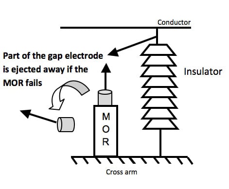
Without the use of a disconnecting device, it is difficult to locate a failed arrester. One possible solution is for an indicating device to be designed into the configuration. In this configuration the indicating device is activated (just like common disconnecting devices of today) by fault current in the event of an EGLA overload and part or all of the gap electrode can fall away or be moved by gravity in some way.
CLICK TO ENLARGE
2. Consistent Gap Spacing
The second issue that needs a resolution for this arrester design is related to setting the gap. All EGLA installations require that the gap be set in the field. This then becomes the responsibility of the installer instead of the manufacturer. Fortunately, the gap spacing for line protection applications can have relatively wide variation and not affect system performance. Still, it is preferable that the spacing be somehow factory set.
Reliability Considerations
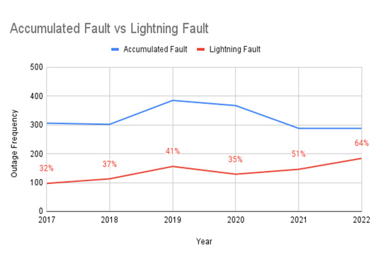
It is a well-known fact that the addition of line arresters can improve or eliminate outages associated with lightning. It is also a fact that in any reliability equation, arrester reliability needs to also be included. In this regard, an arrester having zero probability of causing a long-term outage has always been a desirable goal. The EGLA offers just that. The number of arresters is also a variable in the reliability equation. Generally, more arresters mean a higher probability of an outage due to arrester overload. However, in the case of the EGLA, which has a zero probability of causing a long-term outage, the number of arresters installed does not impact the reliability equation at all.
Economic Considerations
If the EGLA can be manufactured at lower costs due to fewer parts and less materials than un-gapped arresters (as implied in this overview), then it follows that the cost of reliability improvement using the EGLA should become increasingly attractive.
Conclusions
The EGLA has represented a step forward in the never-ending quest to improve lightning induced outage rates on distribution and transmission lines. With potential of being more environmentally friendly, having lower purchase price while offering improved reliability, longer service life and lower life cycle costs, it can indeed be considered the line arrester of the future.

